Mitsubishi Galant (2004+). Manual - part 729


  Index      Mitsubishi     Mitsubishi Galant - service repair manual 2004 year


Search            


Content   ..  727  728  729  730   ..


Mitsubishi Galant (2004+). Manual - part 729


MANUAL A/C DIAGNOSIS

TSB Revision

HEATER, AIR CONDITIONING AND VENTILATION

55A-55

STEP 5. Recheck for diagnostic trouble code.

Check again if the DTC is set.
(1) Turn the ignition switch to the "ON" position.
(2) Check if the DTC is set.
(3) Turn the ignition switch to the "LOCK" (OFF) position.
Q: Is the check result satisfactory?

YES : Replace the A/C-ECU. On completion, check that the 

DTC is not reset.

NO :  A poor connection, open circuit or other intermittent 

malfunction is present in the CAN bus lines between 
the middle-grade multi-center display unit and the 
A/C-ECU (Refer to GROUP 00, How to Use 
Troubleshooting/Inspection Service Points 

P.00-6

).

DTC U1120: Failure Information on Powertrain Control Module (Related to Engine)

CAUTION

If DTC U1120 is set in the A/C-ECU, diagnose the 
CAN main bus line.

CAUTION

Whenever the ECU is replaced, ensure that the 
communication circuit is normal.

CAUTION

The engine control system- related DTC may be 
set when DTC U1120 is set.  (For details refer to 
GROUP 00, Intersystem Affiliated DTC Reference 
Tabl

P.00-16

.) Diagnose the engine control sys-

tem first when the engine control system- related 
DTC is set.

.

TROUBLE JUDGMENT
The A/C-ECU receives engine control sys-
tem-related signal from the powertrain control mod-
ule by the CAN bus lines. If a fail-safe related data is 
contained in the signal from the powertrain control 
module, DTC U1120 will be stored.

.

TECHNICAL DESCRIPTION (COMMENT) 

Current trouble

• The wiring harness wire or connectors may have 

loose, corroded, or damage terminals, or termi-
nals pushed back in the connector, the 
powertrain control module, or the A/C-ECU may 
be defective.

Past trouble

• If DTC U1120 is stored as a past trouble, carry 

out diagnosis with particular emphasis on wiring 
and connector(s) in the CAN bus line between 
the A/C-ECU and the powertrain control module, 
and the power supply system to the powertrain 
control module. If the connectors and wiring are 
normal, and obviously the ECU is the cause of 
the trouble, replace the ECU. If in doubt, do not 
replace the ECU.
NOTE: For a past trouble, you cannot find it by 
the scan tool CAN bus diagnostics even if there is 
a failure in CAN bus lines. In this case, refer to 
GROUP 00, How to Cope with Intermittent Mal-
functions 

P.00-6

.) and check the CAN bus lines. 
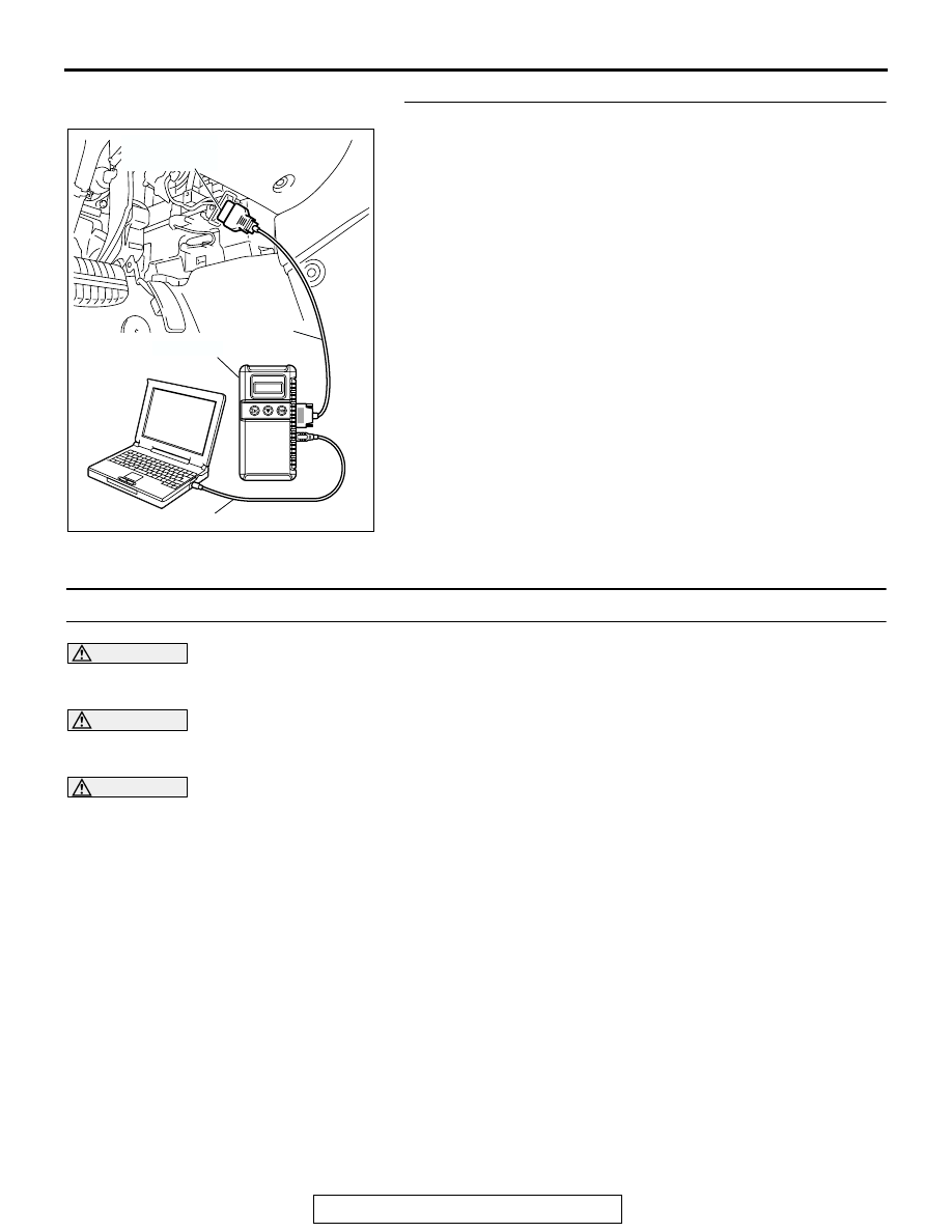
AC305412

AB

MB991910

DATA LINK

CONNECTOR

MB991824

MB991827

MANUAL A/C DIAGNOSIS

TSB Revision

HEATER, AIR CONDITIONING AND VENTILATION

55A-56

You can narrow down the possible cause of the 
trouble by referring to the DTC, which is set 
regarding the CAN communication-linked ECUs 
(Refer to GROUP 54C 

 Explanation about the 

scan tool CAN bus diagnostics 

P.54C-6

).

.

TROUBLESHOOTING HINTS

• Malfunction of the A/C-ECU.

• Malfunction of the powertrain control module.

DIAGNOSIS

Required Special Tool:

•  MB991958: Scan Tool (MUT-III Sub Assembly)

• MB991824: Vehicle Communication Interface (V.C.I.)

• MB991827: MUT-III USB Cable

• MB991910: MUT-III Main Harness A (Vehicles with CAN 

communication system)

STEP 1. Using scan tool MB991958, diagnose the CAN bus 
line.

CAUTION

To prevent damage to scan tool (MUT-III), always turn the 
ignition switch to the "LOCK" (OFF) position before con-
necting or disconnecting scan tool (MUT-III).
(1) Connect scan tool MB991958 to the data link connector.
(2) Turn the ignition switch to the "ON" position.
(3) Diagnose the CAN bus line.
(4) Turn the ignition switch to the "LOCK" (OFF) position.
Q: Is the CAN bus line found to be normal?

YES : Go to Step 2.
NO :  Repair the CAN bus line (Refer to GROUP 54C, 

Diagnosis 

P.54C-14

).

AC305412

AB

MB991910

DATA LINK

CONNECTOR

MB991824

MB991827

MANUAL A/C DIAGNOSIS

TSB Revision

HEATER, AIR CONDITIONING AND VENTILATION

55A-57

STEP 2. Using scan tool MB991958, read the powertrain 
control module diagnostic trouble code.

Check whether any engine or automatic transmission DTCs are 
set or not.
(1) Turn the ignition switch to the "ON" position.
(2) Check for engine and automatic transmission DTCs.
(3) Turn the ignition switch to the "LOCK" (OFF) position.
Q: Is the check result satisfactory?

YES : Go to Step 3.
NO :  Refer to GROUP 13A, Diagnostic Trouble Code 

P.13A-34

 <2.4L> or GROUP 13B, Diagnostic Trouble 

Code 

P.13B-33

 <3.8L>.

STEP 3. Using scan tool MB991958, check for any 
diagnostic trouble code.

Check if a DTC, which relates to CAN communication-linked 
systems below, is set.

• Combination meter

DTC indicating a time-out error related to the engine or 
automatic transmission control system

• ETACS

DTC indicating a time-out error related to the engine or 
automatic transmission control system

• Multi-center display unit (middle grade type) 

DTC indicating a time-out error related to the engine or 
automatic transmission control system

(1) Turn the ignition switch to the "ON" position.
(2) Check for a DTC related to the relevant system.

(3) Turn the ignition switch to the "LOCK" (OFF) position.
Q: Is the check result satisfactory?

YES : Go to Step 5.
NO :  Go to Step 4.

AC305412

AB

MB991910

DATA LINK

CONNECTOR

MB991824

MB991827

AC305412

AB

MB991910

DATA LINK

CONNECTOR

MB991824

MB991827

MANUAL A/C DIAGNOSIS

TSB Revision

HEATER, AIR CONDITIONING AND VENTILATION

55A-58

STEP 4. Recheck for diagnostic trouble code.

Check again if the DTC is set.
(1) Turn the ignition switch to the "ON" position.
(2) Check if the DTC is set.
(3) Turn the ignition switch to the "LOCK" (OFF) position.
Q: Is the check result satisfactory?

YES : Replace the powertrain control module. On 

completion, check that the DTC is not reset.

NO :  There is an intermittent malfunction such as poor 

engaged connector(s) or open circuit (Refer to 
GROUP 00, How to Use Troubleshooting/Inspection 
Service Points

P.00-6

).

STEP 5. Recheck for diagnostic trouble code.

Check again if the DTC is set.
(1) Turn the ignition switch to the "ON" position.
(2) Check if the DTC is set.

(3) Turn the ignition switch to the "LOCK" (OFF) position.
Q: Is the check result satisfactory?

YES : A poor connection, open circuit or other intermittent 

malfunction is present in the lines between the 
powertrain control module and the A/C-ECU (Refer to 
GROUP 00, How to Cope with Intermittent 
Malfunctions 

P.00-6

.)

NO :  Replace the A/C-ECU. On completion, check that the 

DTC is not reset.

AC305412

AB

MB991910

DATA LINK

CONNECTOR

MB991824

MB991827

AC305412

AB

MB991910

DATA LINK

CONNECTOR

MB991824

MB991827


Content   ..  727  728  729  730   ..