Mitsubishi Galant (2004+). Manual - part 728
MANUAL A/C DIAGNOSIS
TSB Revision
HEATER, AIR CONDITIONING AND VENTILATION
55A-51
STEP 5. Recheck for diagnostic trouble code.
Check again if the DTC is set.
1. Turn the ignition switch to the "ON" position.
2. Check if the DTC is set.
3. Turn the ignition switch to the "LOCK" (OFF) position.
Q: Is the check result satisfactory?
YES : A poor connection, open circuit or other intermittent
malfunction is present in the lines between the
powertrain control module and the A/C-ECU (Refer to
GROUP 00E, Harness Connector Inspection
NO : Replace the A/C-ECU. On completion, check that the
DTC is not reset.
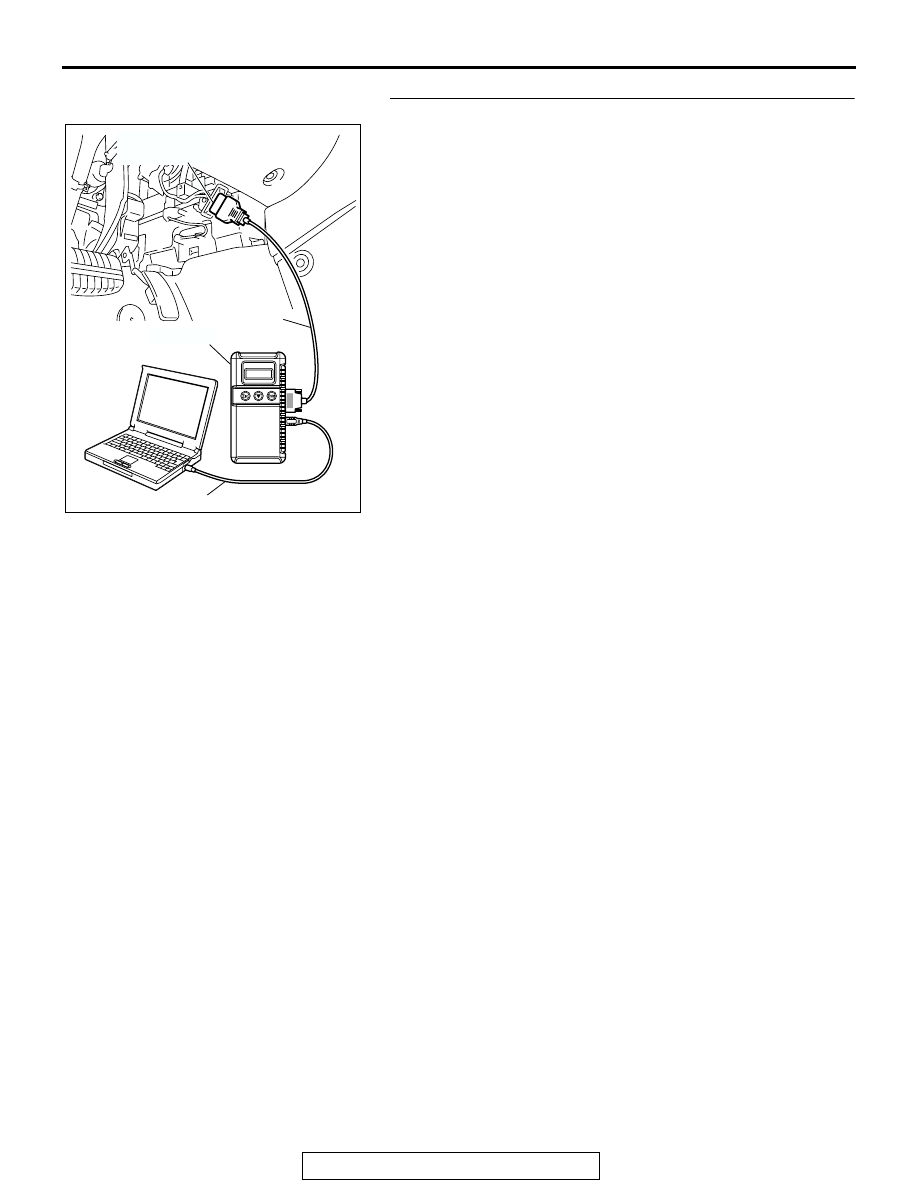
AC305412
AB
MB991910
DATA LINK
CONNECTOR
MB991824
MB991827