Mitsubishi Galant (2004+). Manual - part 716


  Index      Mitsubishi     Mitsubishi Galant - service repair manual 2004 year


Search            


Content   ..  714  715  716  717   ..


Mitsubishi Galant (2004+). Manual - part 716


GENERAL DESCRIPTION

TSB Revision

HEATER, AIR CONDITIONING AND VENTILATION

55A-3

GENERAL DESCRIPTION

M1552000100340

The heater and cooling units are combined in a sin-
gle unit, which, with the mode film damper and flow 
rate control valve in the heater unit, reduces ventila-
tion resistance, increases fan power, and decreases 
noise. 

SAFETY PRECAUTIONS

WARNING

Wear safety goggles and gloves when servic-
ing the refrigeration system to prevent 
severe damage to eyes and hands.

Because R-134a refrigerant is a hydro fluorocarbon 
(HFC) which contains hydrogen atoms in place of 
chlorine atoms, it will not cause damage to the ozone 
layer.
Ozone filters out harmful radiation from the sun. To 
assist in protecting the ozone layer, Mitsubishi 
Motors Corporation recommends an R-134a refriger-
ant recycling device.
Refrigerant R-134a is transparent and colorless in 
both the liquid and vapor state. Since it has a boiling 
point of 

−29.8°C (−21.64°F) at atmospheric pressure, 

it will be a vapor at all normal temperatures and pres-
sures. The vapor is heavier than air, non-flammable, 
and non-explosive. The following precautions must 
be observed when handling R-134a.

WARNING

Do not heat R-134a above 40

°

C (104.0

°

F) or it 

may catch fire and explode.

R-134a evaporates so rapidly at normal atmospheric 
pressures and temperatures that it tends to freeze 
anything it contacts. For this reason, extreme care 
must be taken to prevent any liquid refrigerant from 
contacting the skin and especially the eyes. Always 
wear safety goggles when servicing the refrigeration 
part of the A/C system. Keep a bottle of sterile min-
eral oil handy when working on the refrigeration sys-
tem.

1. Should any liquid refrigerant get into your eyes, 

use a few drops of mineral oil to wash them out. 
R-134a is rapidly absorbed by the oil.

2. Next, splash your eyes with plenty of cold water.
3. Call your doctor immediately even if irritation has 

ceased.

CAUTION

Keep R-134a containers upright when charging 
the system.
In most instances, moderate heat is required to bring 
the pressure of the refrigerant in its container above 
the pressure of the system when charging or adding 
refrigerant.
A bucket or large pan of hot water not over 40

°C 

(104.0

°F) is all the heat required for this purpose. Do 

not heat the refrigerant container with a blow torch or 
any other means that would raise temperature and 
pressure above this temperature. Do not weld or 
steam-clean on or near the system components or 
refrigerant lines.

WARNING

The leak detector for R-134a should be used 
to check for refrigerant gas leaks.

CAUTION

Do not allow liquid refrigerant to touch bright 
metal or it will be stained.
When metering R-134a into the refrigeration system, 
keep the supply tank or cans in an upright position. If 
the refrigerant container is on its side or upside 
down, liquid refrigerant will enter the system and 
damage the compressor.
Refrigerant will tarnish bright metal and chrome sur-
faces, and in combination with moisture can severely 
corrode all metal surfaces.
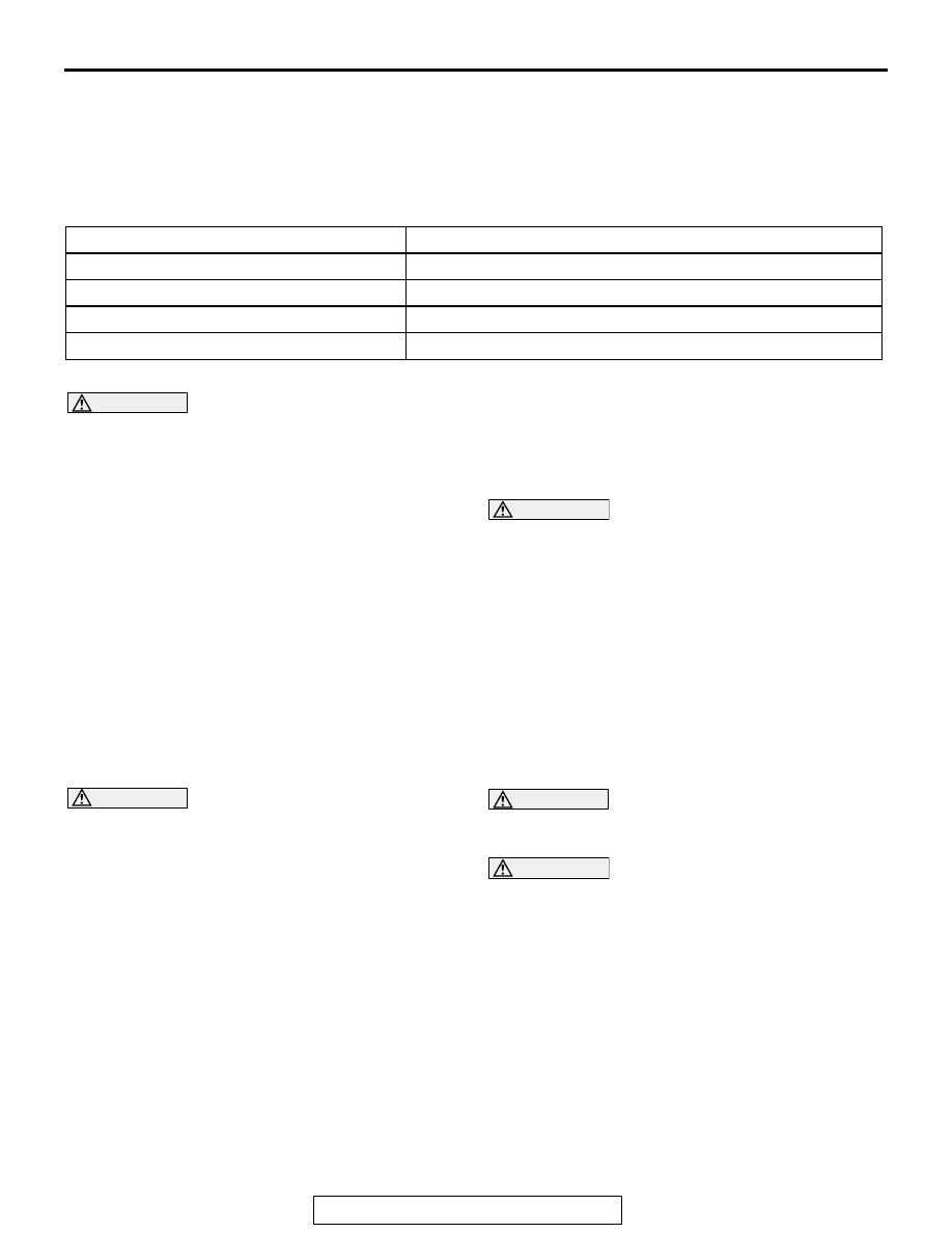
ITEM

SPECIFICATION

Heater control assembly

Dial type

Compressor

MSC105CA

Compressor Model

Scroll type

Refrigerant and quantity g (oz)

R-134a (HFC-134a), 590 

− 630 (20.80 − 22.22)

GENERAL DESCRIPTION

TSB Revision

HEATER, AIR CONDITIONING AND VENTILATION

55A-4

OPERATION

.

CONDENSER FAN AND RADIATOR FAN CON-
TROL
The PCM judges the required revolution speed of 
radiator fan motor and condenser fan motor using 
the input signals transmitted from A/C switch, output 
shaft speed sensor and engine coolant temperature 
sensor. The PCM activates the fan control relays  to 
drive the radiator fan motor and condenser fan 
motor.

.

COMPRESSOR CONTROL

When operating the air conditioning switch

• The air thermo sensor, which senses the temper-

ature of the air flowing out of the evaporator, 
deactivates the compressor at 3

°C (37.4°F) or 

below.

• The dual pressure switch turns OFF when the 

refrigerant pressure becomes excessively high or 
low, thus protecting the compressor circuit (See 
Table below).

• When the air thermo sensor is activated, and the 

ignition switch, blower switch, and air condition-
ing switch are ON, the A/C compressor clutch 
relay is energized.

When operating the mode selection dial

• The air conditioning will work when the mode 

selection dial is set to the "Defroster" or 
"Defroster/foot" position, or the temperature con-
trol dial is set to the "MAX A/C" position. In other 
dial positions, when the air conditioning switch is 
turned on, the air conditioning will work.

A/C Compressor Clutch Relay ON Conditions

Ignition switch (IG2)

ON

NOTE: A/C compressor clutch relay is 
de-energized when any one switch, sensor 
or control unit shown on the left turns off.
NOTE:  The components marked by 

*


communicate with the PCM. If the air thermo 
sensor detects a temperature of 3

°

(37.4

°

F), the A/C-ECU will turn off the A/C 

compressor clutch relay.

Blower switch

ON

Air conditioning switch, mode selection dial 
defroster, defroster/foot position or temperature 
control MAX A/C

ON

Air thermo sensor

*

Pressure detected 
by A/C pressure 
sensor

2.94 MPa or less (If the 
refrigerant pressure exceeds 
2.94 MPa, A/C compressor 
clutch relay is not ON 
condition until the refrigerant 
pressure has been measured 
up to 2.35 MPa or less.)                                                                                                                                   

ON

0.19 MPa or more (If the 
refrigerant pressure falls short 
of  0.19 MPa, A/C compressor 
clutch relay is not ON 
condition until the refrigerant 
pressure has been measured 
up to 0.22  MPa or more.)

A/C compressor clutch relay driving transistor (within 
powertrain control module)

ON

SERVICE PRECAUTIONS

TSB Revision

HEATER, AIR CONDITIONING AND VENTILATION

55A-5

SERVICE PRECAUTIONS

CAUTION LABELS

M1552017400097

The refrigerant gas warning label must be affixed in the location 
shown in the figure on the left. Follow the instructions on the 
label when servicing.

MANUAL A/C DIAGNOSIS

INTRODUCTION TO HEATER, AIR CONDITIONING AND VENTILATION DIAGNOSIS

M1552012200333

Air is drawn into the heater assembly from either the 
outside, or from the inside of the passenger cabin if 
DEFROST, maximum cooling or RECIRCULATION 
are selected. The air is then forced through the evap-
orator where heat is removed, cooling and de-humid-
ifying the air. Depending on the temperature 
selected, a portion of this air is then forced through 
the heater core to achieve the selected discharge 
temperature.

If the system does not cool properly, look for a prob-
lem with the refrigerant, blower or air distribution sys-
tems. If the system does not heat properly, look for a 
problem with the coolant, blower or air distribution 
systems. In either case all system fuses, circuit 
breaker and relays should be checked.

HEATER, AIR CONDITIONING AND VENTILATION DIAGNOSTIC TROUBLESHOOTING 
STRATEGY

M1552009600386

Use these steps to plan your diagnostic strategy. If 
you follow them carefully, you will be sure that you 
have exhausted most of the possible ways to find a 
heater, air conditioning and ventilation fault.
1. Gather information from the customer.

2. Verify that the condition described by the 

customer exists.

3. Find the malfunction by following the Symptom 

Chart.

4. Verify that the malfunction is eliminated.

No.

Contents

1

Name of air conditioner manufacturer

2

Amount of refrigerant

3

Name of compressor oil

4

Parts number

AC306336

AC306936

AB

AC200079

1

2

3

3

2

AB

4

MANUAL A/C DIAGNOSIS

TSB Revision

HEATER, AIR CONDITIONING AND VENTILATION

55A-6

DIAGNOSTIC FUNCTION

M1552019800035

HOW TO CONNECT THE SCAN TOOL (MUT-III)

Required Special Tool:

•  MB991958: Scan Tool (MUT-III Sub Assembly)

• MB991824: Vehicle Communication Interface (V.C.I.)

• MB991827: MUT-III USB Cable

• MB991910: MUT-III Main Harness A (Vehicles with CAN 

communication system)

CAUTION

To prevent damage to scan tool MB991958, always turn the 
ignition switch to the "LOCK" (OFF) position before con-
necting or disconnecting scan tool MB991958.
1. Ensure that the ignition switch is at the "LOCK" (OFF) 

position.

2. Start up the personal computer.
3. Connect special tool MB991827 to special tool MB991824 

and the personal computer.

4. Connect special tool MB991910 to special tool MB991824
5. Connect special tool MB991910 to the data link connector.
6. Turn the power switch of special tool MB991824 to the "ON" 

position.
NOTE: When the special tool MB991824 is energized, the 
special tool MB991824 indicator light will be illuminated in a 
green color.

7. Start the MUT-III system on the personal computer.
NOTE: Disconnecting the scan tool special tool MB991824 is 
the reverse of the connecting sequence, making sure that the 
ignition switch is at the "LOCK" (OFF) position.

HOW TO READ AND ERASE DIAGNOSTIC 
TROUBLE CODES

Required Special Tool:

•  MB991958: Scan Tool (MUT-III Sub Assembly)

• MB991824: Vehicle Communication Interface (V.C.I.)

• MB991827: MUT-III USB Cable

• MB991910: MUT-III Main Harness A (Vehicles with CAN 

communication system)

AC305412

AB

MB991910

DATA LINK

CONNECTOR

MB991824

MB991827


Content   ..  714  715  716  717   ..