Mitsubishi Galant (2004+). Manual - part 584
INTAKE MANIFOLD AND WATER PUMP
TSB Revision
ENGINE OVERHAUL <2.4L ENGINE>
11B-25
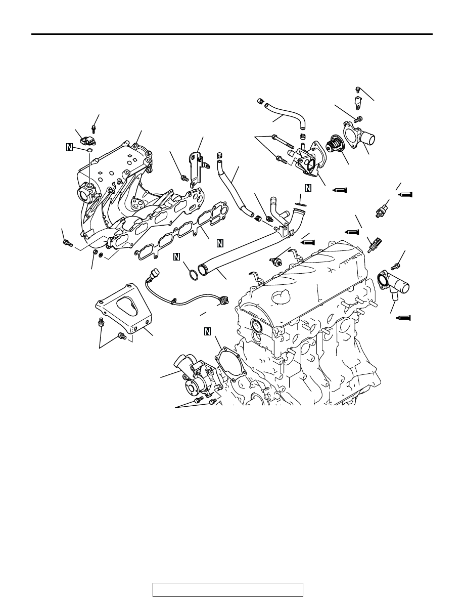
INTAKE MANIFOLD AND WATER PUMP
REMOVAL AND INSTALLATION
M1113025500034
Required Special Tool:
• MD998054: Oil Pressure Switch Wrench
AK303215 AB
1
2
3
4
5
6
7
10
11
12
8
13
14
15
16
17
20
21
20 ± 2 N·m
15 ± 1 ft-lb
24 ± 3 N·m
18 ± 1 ft-lb
14 ± 1 N·m
124 ± 8 in-lb
13 ± 2 N·m
115 ± 17 in-lb
24 ± 4 N·m
18 ± 2 ft-lb
31 ± 3 N·m
23 ± 2 ft-lb
23 ± 2 N·m
17 ± 1 ft-lb
19 ± 3 N·m
14 ± 2 ft-lb
13 ± 2 N·m
115 ± 17 in-lb
30 ± 9 N·m
22 ± 6 ft-lb
24 ± 3 N·m
18 ± 1 ft-lb
5.0 ± 1.0 N·m
45 ± 8 in-lb
13 ± 2 N·m
115 ± 17 in-lb
11 ± 1 N·m
98 ± 8 in-lb
18
19
10 ± 2 N·m
89 ± 17 in-lb
REMOVAL STEPS
1. WATER HOSE
2. WATER HOSE
3. WATER PUMP
4. WATER PUMP GASKET
>>H<<
5. O-RING
>>H<<
6. WATER INLET PIPE
>>H<<
7. O-RING
>>G<<
8. INTAKE MANIFOLD STAY
9. WATER INLET FITTING
>>F<<
10. THERMOSTAT
>>E<<
11. THERMOSTAT HOUSING
12. MANIFOLD ABSOLUTE PRESSURE
SENSOR
13. INTAKE MANIFOLD
14. INTAKE MANIFOLD GASKET
15. ENGINE HANGER
16. KNOCK SENSOR
>>D<<
17. ENGINE OIL PRESSURE SWITCH
<<A>> >>C<<
18 ENGINE OIL PRESSURE SWITCH
>>B<<
19. ENGINE COOLANT TEMPERATURE
SENSOR
>>A<<
20. WATER OUTLET FITTING
REMOVAL STEPS (Continued)