Mitsubishi Galant (2004+). Manual - part 580
EXHAUST MANIFOLD
TSB Revision
ENGINE OVERHAUL <2.4L ENGINE>
11B-9
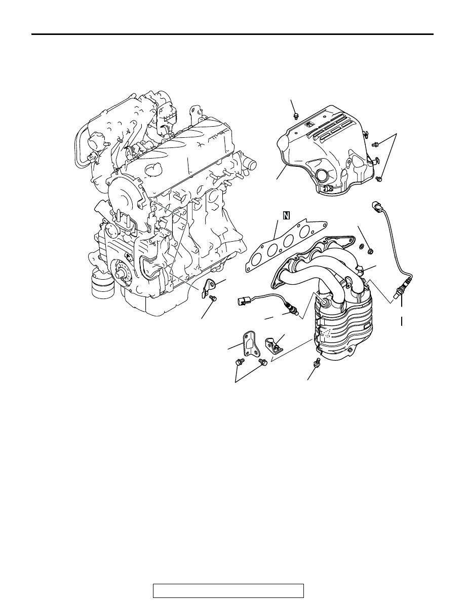
EXHAUST MANIFOLD
REMOVAL AND INSTALLATION
M1113004900457
Required Special Tools:
• MD998770: Oxygen Sensor Wrench
AK303212
1
2
3
4
8
5
6
7
34 ± 5 N·m
26 ± 2 ft-lb
36 ± 5 N·m
27 ± 3 ft-lb
44 ± 5 N·m
33 ± 3 ft-lb
49 ± 5 N·m
36 ± 3 ft-lb
14 ± 1 N·m
124 ± 8 in-lb
24 ± 3 N·m
18 ± 1 ft-lb
14 ± 1 N·m
124 ± 8 in-lb
44 ± 5 N·m
33 ± 3 ft-lb
AB
REMOVAL STEPS
1. ENGINE HANGER
<<A>> >>B<<
2. OXYGEN SENSOR
<<A>> >>B<<
3. OXYGEN SENSOR
4. EXHAUST MANIFOLD COVER
5. EXHAUST MANIFOLD BRACKET
"B"
6. EXHAUST MANIFOLD
7. EXHAUST MANIFOLD GASKET
8. EXHAUST MANIFOLD BRACKET
"A"
REMOVAL STEPS (Continued)