Mitsubishi Galant (2004+). Manual - part 518
ANTI-LOCK BRAKING SYSTEM (ABS) DIAGNOSIS
TSB Revision
ANTI-LOCK BRAKING SYSTEM (ABS)
35B-17
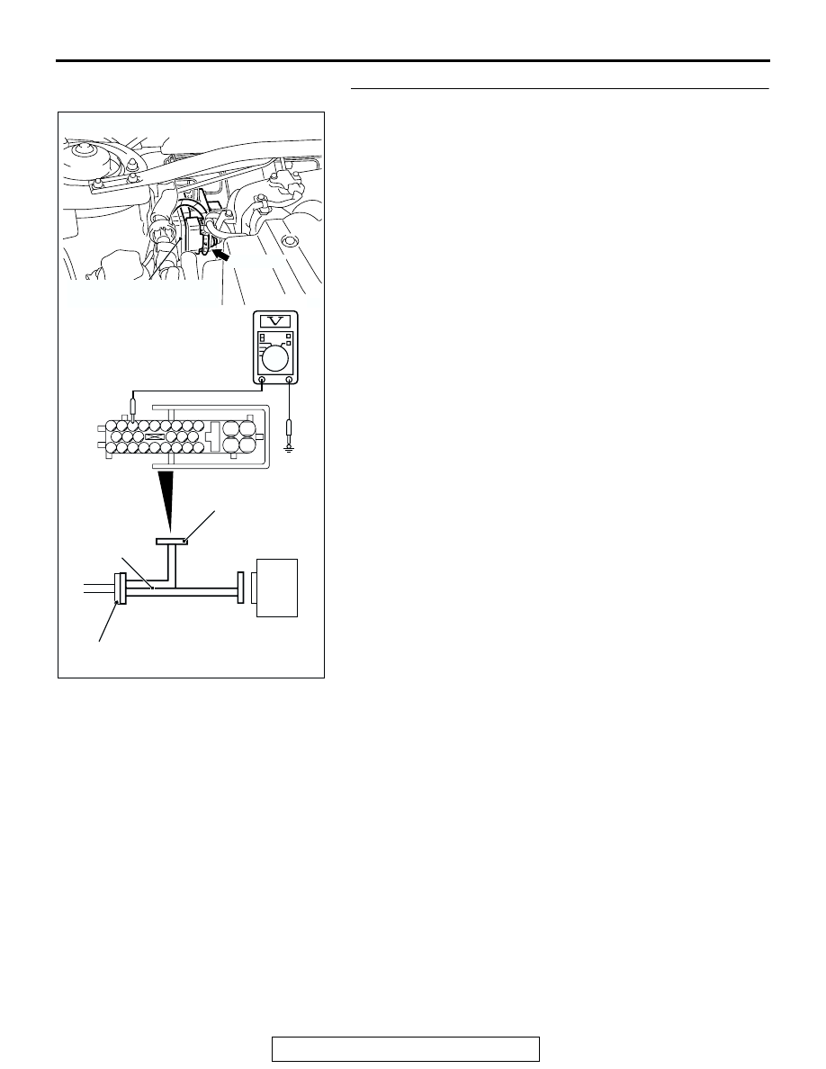
STEP 4. Measure the voltage at ABS-ECU connector A-02.
(1) Disconnect the connector A-02, and connect special tool
ABS Check Harness (MB991970) to the wiring
harness-side connector.
NOTE: Do not connect special tool ABS Check Harness
(MB991970) to the ABS-ECU.
(2) Turn the ignition switch to the "ON" position.
(3) Measure the voltage between the relevant signal and
ground terminals in the wheel speed sensor circuit and
body ground. It should be less than 1V.
• DTC C1201 is set: Between signal terminal 9 and body
ground, and between ground terminal 10 and body
ground
• DTC C1206 is set: Between signal terminal 26 and body
ground, and between ground terminal 16 and body
ground
• DTC C1211 is set: Between signal terminal 11 and body
ground, and between ground terminal 17 and body
ground
• DTC C1216 is set: Between signal terminal 28 and body
ground, and between ground terminal 27 and body
ground
Q: Does the voltage measure 1 V or less?
YES : Go to Step 5.
NO (When the voltage between terminal 9 or 10
− and
body ground measures more than 1 V) : Go to Step 7.
NO (When the voltage between terminal 26 or 16
− and
body ground measures more than 1 V) : Go to Step 9.
NO (When the voltage between terminal 11 or 17
− and
body ground measures more than 1 V) : Go to Step 11.
NO (When the voltage between terminal 28 or 27
− and
body ground measures more than 1 V) : Go to Step 13.
AC306403
19
2
18
1
8
9
7
6
5
4
3
10
11
25
15
16
17
27
28
26
12
13
14
23
24
22 21 20
AB
ABS-ECU
MB991970
CHECK CONNECTOR
A-02 HARNESS
CONNECTOR
A-02 (GR)
CONNECTOR: A-02
HYDRAULIC UNIT
(WITH BUILT-IN ABS-ECU)