Mitsubishi Galant (2004+). Manual - part 517


  Index      Mitsubishi     Mitsubishi Galant - service repair manual 2004 year


Search            


Content   ..  515  516  517  518   ..


Mitsubishi Galant (2004+). Manual - part 517


ANTI-LOCK BRAKING SYSTEM (ABS) DIAGNOSIS

TSB Revision

ANTI-LOCK BRAKING SYSTEM (ABS)

35B-13

DIAGNOSTIC TROUBLE CODE PROCEDURES

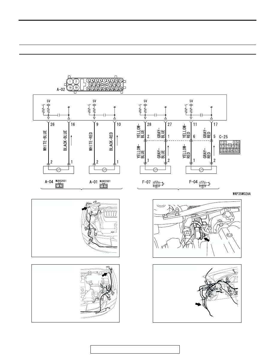
DTC C1200/C1205/C1210/1215 Wheel Speed Sensor (Open circuit or short circuit)

WHEEL SPEED SENSOR

WHEEL SPEED SENSOR

(REAR: RH)

(REAR: LH)

(FRONT: RH)

(FRONT: LH)

ABS-ECU

Wheel Speed Sensor Circuit

AC305206

A-01 (B)

CONNECTOR: A-01

AT

AC304742

A-02 (GR)

CONNECTOR: A-02

HYDRAULIC UNIT
(WITH BUILT-IN ABS-ECU)

AC

AC305210AI

A-04(B)

CONNECTOR: A-04

AC305231BL

CONNECTOR: C-25

C-25

ANTI-LOCK BRAKING SYSTEM (ABS) DIAGNOSIS

TSB Revision

ANTI-LOCK BRAKING SYSTEM (ABS)

35B-14

CAUTION

If there is any problem in the CAN bus lines, an 
incorrect diagnostic trouble code may be set. 
Diagnose the CAN bus lines before the DTC 
(Refer to GROUP 54C, Trouble code diagno-
sis

P.54C-12

).

.

CIRCUIT OPERATION

• A toothed wheel speed rotor generates a voltage 

pulse as it moves across the pickup field of each 
wheel speed sensor.

• The amount of voltage generated at each wheel 

is determined by the clearance between the 
wheel speed rotor teeth and the wheel speed 
sensor, and by the speed of rotation.

• Sends alternating current signals at frequencies 

which are proportional to the rotation speeds of 
each wheel to the ABS electronic control unit 
(ABS-ECU).

• The ABS hydraulic unit modulates the amount of 

braking force individually applied to each wheel 
cylinder.

.

ABS DTC SET CONDITIONS
The ABS-ECU monitors voltage fluctuation in each 
wheel speed sensor circuit. If the ECU detects a 
short or open circuit in the circuit, it will set a diag-
nostic trouble code.

.

TROUBLESHOOTING HINTS (The most likely 
causes for these DTCs are to set are:)

Current trouble

• Malfunction of the wheel speed sensor

• Damaged wiring harness or connector

• Malfunction of the hydraulic unit (integrated with 

ABS-ECU)

Past  trouble

• Carry out diagnosis with particular emphasis on 

connector(s) or wiring harness in wheel speed 
sensor circuit. For diagnosis procedures, refer to 
"How to cope with past trouble" (Refer to GROUP 
00, How to use Troubleshooting/Inspection Ser-
vice Points

P.00-6

).

.

DIAGNOSIS

Required Special Tools:

• MB991958: Scan Tool (MUT-III Sub Assembly)

• MB991824: Vehicle Communication Interface (V.C.I.)

• MB991827: MUT-III USB Cable

• MB991910: MUT-III Main Harness A

• MB991970: ABS Check Harness

.

AC305260

F-04

F-07

CONNECTORS: F-04, F-07

AB

ANTI-LOCK BRAKING SYSTEM (ABS) DIAGNOSIS

TSB Revision

ANTI-LOCK BRAKING SYSTEM (ABS)

35B-15

STEP 1. Using scan tool MB991958, diagnose the CAN bus 
line.

CAUTION

To prevent damage to scan tool MB991958, always turn the 
ignition switch to the "LOCK" (OFF) position before con-
necting or disconnecting scan tool MB991958.
(1) Connect scan tool MB991958 to the data link connector.
(2) Turn the ignition switch to the "ON" position.
(3) Diagnose the CAN bus line.
(4) Turn the ignition switch to the "LOCK" (OFF) position.
Q: Is the CAN bus line found to be normal?

YES : Go to Step 3
NO :  Repair the CAN bus line (Refer to GROUP 54C, 

Diagnosis 

P.54C-14

). Then go to Step 2.

STEP 2. Recheck for diagnostic trouble code.

CAUTION

To prevent damage to scan tool MB991958, always turn the 
ignition switch to the "LOCK" (OFF) position before con-
necting or disconnecting scan tool MB991958.
(1) Turn the ignition switch to the "ON" position.
(2) Erase the DTC.

(3) Turn the ignition switch to the "LOCK" (OFF) position.
(4) Turn the ignition switch to the "ON" position.
(5) Check if the DTC is set.
(6) Turn the ignition switch to the "LOCK" (OFF) position.
Q: Is DTC C1200, C1205, C1210 or C1215 set?

YES : Go to Step 3
NO :  The procedure is complete.

AC305412

AB

MB991910

DATA LINK

CONNECTOR

MB991824

MB991827

AC305412

AB

MB991910

DATA LINK

CONNECTOR

MB991824

MB991827

ANTI-LOCK BRAKING SYSTEM (ABS) DIAGNOSIS

TSB Revision

ANTI-LOCK BRAKING SYSTEM (ABS)

35B-16

STEP 3. Using scan tool MB991958, check data list.

CAUTION

To prevent damage to scan tool MB991958, always turn the 
ignition switch to the "LOCK" (OFF) position before con-
necting or disconnecting scan tool MB991958.
(1) Connect scan tool MB991958 to the data link connector.
(2) Start the engine.
(3) Set scan tool MB991958 to the data reading mode, and 

check the data list items by driving the vehicle.

• Item 01 (DTC C1200 is set): Front right wheel speed 

sensor

• Item 02 (DTC C1205 is set): Front left wheel speed sen-

sor

• Item 03 (DTC C1210 is set): Rear right wheel speed 

sensor

• Item 04 (DTC C1215 is set): Rear left wheel speed sen-

sor

(4) Turn the ignition switch to the "LOCK" (OFF) position.
Q: Does the speedometer indication match the scan tool 

indication?
YES : 
It can be assumed that this malfunction is intermittent. 

Refer to GROUP 00, How to Use 
Troubleshooting/Inspection Service Points 

− How to 

Cope with Intermittent Malfunction 

P.00-6

.

NO :  Go to Step 4.

AC305412

AB

MB991910

DATA LINK

CONNECTOR

MB991824

MB991827


Content   ..  515  516  517  518   ..