Mitsubishi Galant (2004+). Manual - part 503
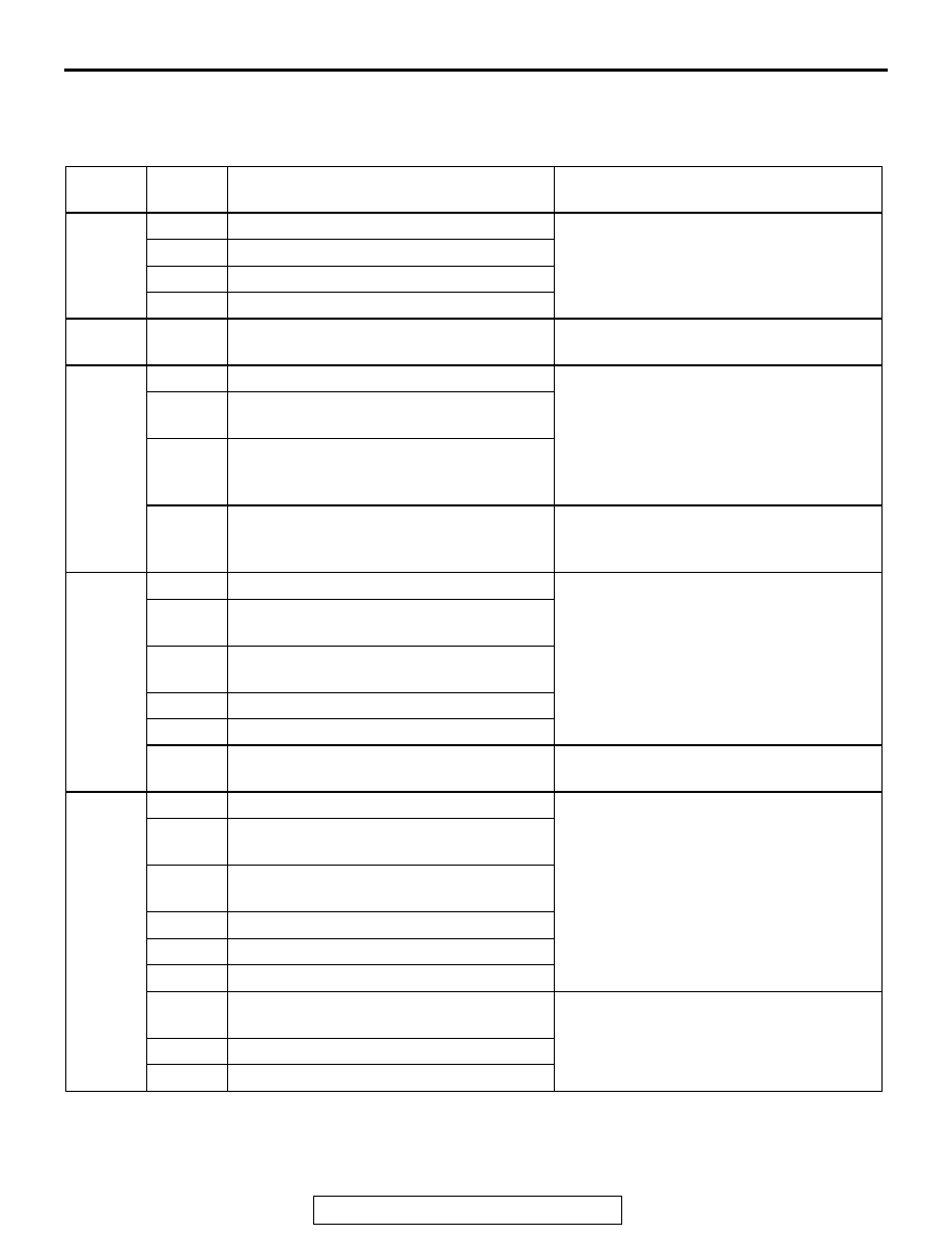
CAN COMMUNICATION-RELATED DTC CODE (U CODE) TABLE
TSB Revision
CONTROLLER AREA NETWORK (CAN)
54C-623
CAN COMMUNICATION-RELATED DTC CODE (U CODE)
TABLE
M1548300300052
OUTPUT
ECU
CODE
NO.
DIAGNOSTIC ITEM
ACTION
Power
train
control
module
U1073
Bus Off
CAN main bus line diagnostics
U1102
ABS-ECU time-out
U1108
Combination meter time-out
U1110
A/C-ECU time-out
ABS-EC
U
U1073
Bus Off
CAN main bus line diagnostics
ABS/TC
L-ECU
U1073
Bus Off
CAN main bus line diagnostics
U1100
Powertrain control module time-out
(related to engine) <vehicles with TCL>
U1101
Powertrain control module time-out
(related to automatic transmission)
<vehicles with TCL>
U1120
Failure information on powertrain control
module (related to engine) <vehicles with
TCL>
Diagnose CAN main bus lines and
confirm input signals.
Combina
tion
meter
U1073
Bus Off
CAN main bus line diagnostics
U1100
Power train control module time-out
(related to engine)
U1101
Power train control module time-out
(related to A/T)
U1102
ABS-ECU time-out
U1109
ETACS-ECU time-out
U1120
Failure information on power train control
module (related to engine)
Diagnose CAN main bus lines and
confirm input signals.
Multi-cen
ter
display
unit
(middle-
grade
type)
010
Bus Off
CAN main bus line diagnostics
011
Power train control module time-out
(related to engine)
012
Power train control module time-out
(related to A/T)
013
A/C-ECU time-out
014
Combination meter time-out
019
ETACS-ECU time-out
020
Failure information on power train control
module (related to engine)
Diagnose CAN main bus lines and
confirm input signals.
021
Failure information on combination meter
022
Failure information on A/C-ECU