Mitsubishi Galant (2004+). Manual - part 469


  Index      Mitsubishi     Mitsubishi Galant - service repair manual 2004 year


Search            


Content   ..  467  468  469  470   ..


Mitsubishi Galant (2004+). Manual - part 469


DIAGNOSIS

TSB Revision

CONTROLLER AREA NETWORK (CAN)

54C-487

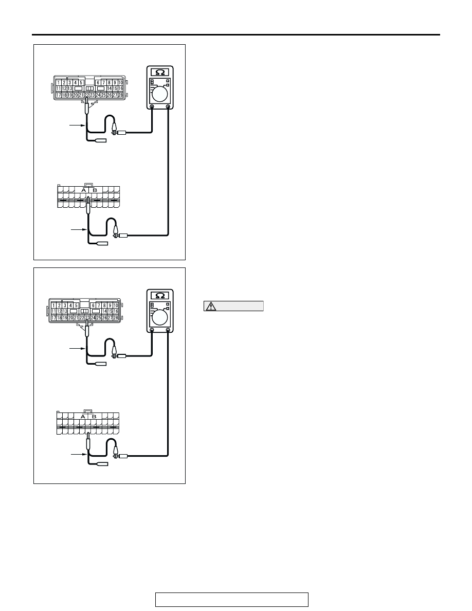
(4) Measure the resistance between intermediate connector 

terminal 22 and SRS-ECU connector terminal 32.

OK: 2 ohms or less

(5) Measure the resistance between intermediate connector 

terminal 23 and SRS-ECU connector terminal 43.

OK: 2 ohms or less

CAUTION

Strictly observe the specified wiring harness repair proce-
dure. For details refer to 

P.54C-5

.

Q: Do all the resistances measure 2 ohms or less?

YES  : If all the resistances measure 2 ohms or less, go to 

Step 18.

NO  :  If either of the resistances measures more than 2 

ohms or all the resistances measure more than 2 
ohms, repair the wiring harness between intermediate 
connector and the SRS-ECU connector. 

AC204582

48

21

22

23

24

25

26

27

28

29

30

31

32

33

34

35

36

37

38

39

40

41

42

43

44

45

46

47

AC204582

TEST 
HARNESS

CC

TEST 
HARNESS

MALE SIDE: C-22

HARNESS SIDE: C-121

AC204582

48

21

22

23

24

25

26

27

28

29

30

31

32

33

34

35

36

37

38

39

40

41

42

43

44

45

46

47

AC204582

TEST 
HARNESS

CB

TEST 
HARNESS

MALE SIDE: C-22

HARNESS SIDE: C-121

DIAGNOSIS

TSB Revision

CONTROLLER AREA NETWORK (CAN)

54C-488

STEP 18. Check the CAN bus lines between joint 
connector (3) and the intermediate connector. Measure the 
resistance between joint connector (3) C-02 and 

intermediate connector C-22.

CAUTION

A digital multimeter should be used. For details refer to 

P.54C-4

.

CAUTION

The test wiring harness should be used. For details refer to 

P.54C-4

.

(1) Disconnect joint connector (3) C-02 and intermediate 

connector C-22, and measure the resistance at the wiring 
harness sides of joint connector (3) C-02 and intermediate 
connector C-22.

(2) Turn the ignition switch to the "LOCK" (OFF) position.

CAUTION

Disconnect the negative battery terminal. For details refer 
to 

P.54C-4

.

(3) Disconnect the negative battery terminal.

AC305231AP

CONNECTOR: C-02

AC305233 AI

CONNECTOR: C-22

C-22 (Y)

DIAGNOSIS

TSB Revision

CONTROLLER AREA NETWORK (CAN)

54C-489

(4) Measure the resistance between joint connector (3) 

terminal 3 and intermediate connector terminal 22.

OK: 2 ohms or less

(5) Measure the resistance between joint connector (3) 

terminal 14 and intermediate connector terminal 23.

OK: 2 ohms or less

CAUTION

Strictly observe the specified wiring harness repair proce-
dure. For details refer to 

P.54C-5

.

Q: Do all the resistances measure 2 ohms or less?

YES  : If all the resistances measure 2 ohms or less, power 

supply to the SRS-ECU may be suspected. Diagnose 
the supplemental restraint system. Refer to GROUP 
52B, SRS air bag diagnosis, equipment diagnosis 

P.52B-30

.

NO  :  If either of the resistances measures more than 2 

ohms or all the resistances measure more than 2 
ohms, repair the wiring harness between joint 
connector (3) and the intermediate connector. 

AC204582

AC204582

HARNESS SIDE: C-02

TEST 
HARNESS

CE

11

22

10

21

9

20

8

19

7

18

6

17

5

16

4

15

3

14

2

13

1

12

TEST 
HARNESS

FEMALE SIDE: C-22

AC204582

AC204582

11

22

10

21

9

20

8

19

7

18

6

17

5

16

4

15

3

14

2

13

1

12

TEST 
HARNESS

CD

TEST 
HARNESS

HARNESS SIDE: C-02

FEMALE SIDE: C-22

DIAGNOSIS

TSB Revision

CONTROLLER AREA NETWORK (CAN)

54C-490

STEP 19. Check the CAN bus lines between joint 
connector (3) and the data link connector. Measure the 
resistance between joint connector (3) C-02 and data link 

connector C-125.

CAUTION

A digital multimeter should be used. For details refer to 

P.54C-4

.

CAUTION

The test wiring harness should be used. For details refer to 

P.54C-4

.

(1) Disconnect joint connector (3) C-02, and measure the 

resistance between the wiring harness side connector of 
joint connector (3) C-02 and wiring harness side connector 
of data link connector C-125.

(2) Turn the ignition switch to the "LOCK" (OFF) position.

CAUTION

Disconnect the negative battery terminal. For details refer 
to 

P.54C-4

.

(3) Disconnect the negative battery terminal.

AC305232

C-125

CONNECTORS: C-02, C-125

AF

C-02

C-02

C-125 (B)


Content   ..  467  468  469  470   ..