Mitsubishi Galant (2004+). Manual - part 464


  Index      Mitsubishi     Mitsubishi Galant - service repair manual 2004 year


Search            


Content   ..  462  463  464  465   ..


Mitsubishi Galant (2004+). Manual - part 464


DIAGNOSIS

TSB Revision

CONTROLLER AREA NETWORK (CAN)

54C-467

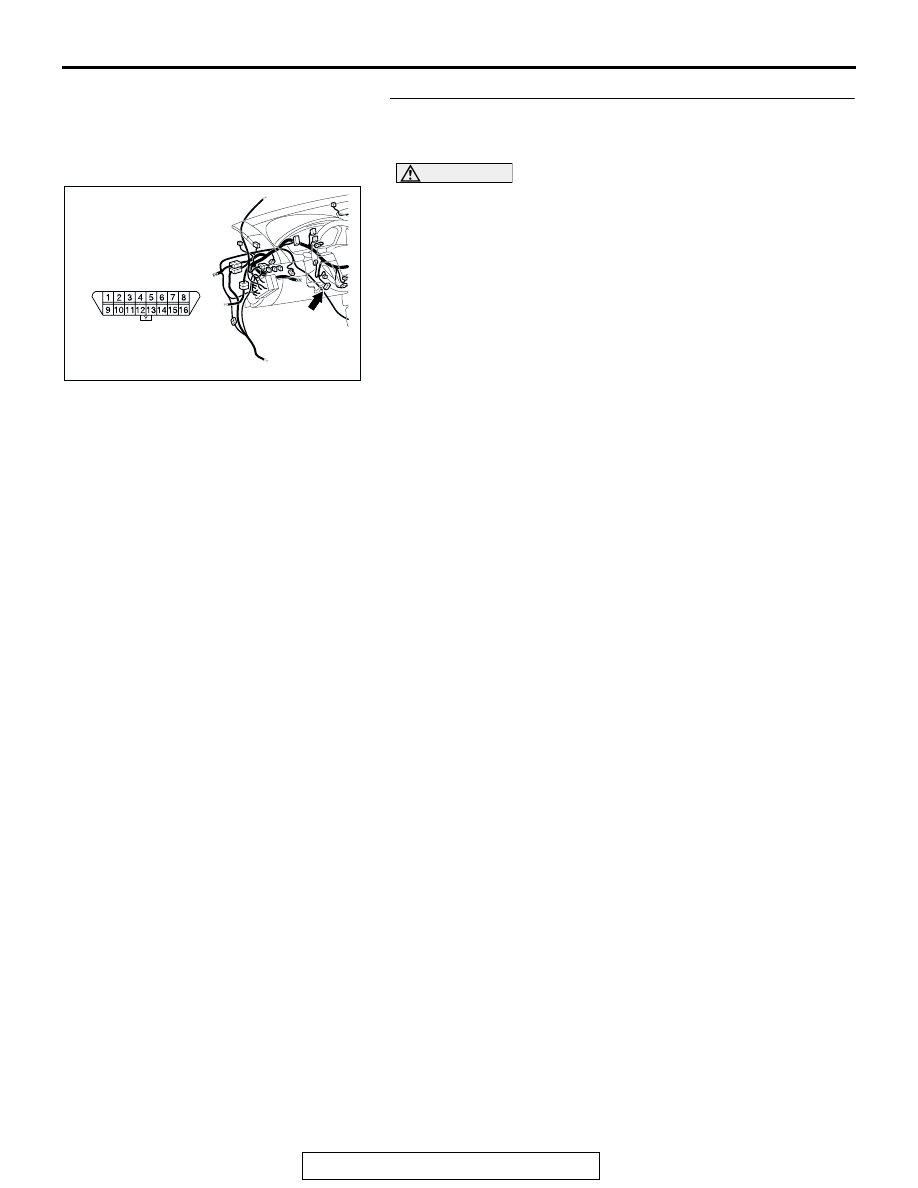
STEP 1. Check data link connector C-125 for loose, 
corroded or damaged terminals, or terminals pushed back 
in the connector.

CAUTION

The strand end of the twisted wire should be within 10 cm 
(4 inches) from the connector. For details refer to 

P.54C-4

.

Q: Is data link connector C-125 in good condition?

YES : Go to Step 2.
NO :  Repair the damaged parts.

AC305231AR

CONNECTOR: C-125

C-125 (B)

DIAGNOSIS

TSB Revision

CONTROLLER AREA NETWORK (CAN)

54C-468

STEP 2. Check the CAN bus lines at the data link 
connector. Measure the resistance at the data link 

connector C-125.

CAUTION

A digital multimeter should be used. For details refer to 

P.54C-4

.

CAUTION

The test wiring harness should be used. For details refer to 

P.54C-4

.

(1) Measure the resistance at the data link connector.
(2) Turn the ignition switch to the "LOCK" (OFF) position.

CAUTION

Disconnect the negative battery terminal. For details refer 
to 

P.54C-4

.

(3) Disconnect the negative battery terminal.

(4) Measure the resistance between data link connector 

terminals 6 and 14.

Q: How much resistance is measured?

2 ohms or less : Diagnostic Item 7: Check the CAN_L and 

H lines for a short circuit. Refer to 

P.54C-313

No continuity : Diagnostic Item 10: Diagnose terminator 

resistors at both ends. Refer to 

P.54C-399

More than 2 ohms but continuity exists : Go to Step 3.

AC305231AR

CONNECTOR: C-125

C-125 (B)

AC204740

AC204740

AC204740

AC204740

AC204740

AC204740

AC204740

AC204740

AC204740DA

TEST 
HARNESS

TEST 
HARNESS

HARNESS SIDE: C-125

DIAGNOSIS

TSB Revision

CONTROLLER AREA NETWORK (CAN)

54C-469

STEP 3. Check intermediate connector C-29 for loose, 
corroded or damaged terminals, or terminals pushed back 
in the connector.

CAUTION

The strand end of the twisted wire should be within 10 cm 
(4 inches) from the connector. For details refer to 

P.54C-4

.

Q: Is intermediate connector C-29 in good condition?

YES : Go to Step 4.
NO :  Repair the damaged parts.

AC305231AI

CONNECTOR: C-29

DIAGNOSIS

TSB Revision

CONTROLLER AREA NETWORK (CAN)

54C-470

STEP 4. Using scan tool MB991958, diagnose the CAN bus 
line (Disconnect intermediate connector C-29, and then 
determine that a failure is present at either the front wiring 
harness side or the instrument panel wiring harness side).

(1) Disconnect intermediate connector C-29.

CAUTION

To prevent damage to scan tool MB991958, always turn the 
ignition switch to the "LOCK" (OFF) position before con-
necting or disconnecting scan tool MB991958.

(2) Connect scan tool MB991958 to the data link connector.
(3) Turn the ignition switch to the "ON" position.

(4) Diagnose CAN bus lines, and check if the MUT-III screen is 

as shown in the illustration.

(5) Turn the ignition switch to the "LOCK" (OFF) position.
(6) Connect intermediate connector C-29.
Q: Does the MUT-III screen correspond to the illustration?

YES : If the MUT-III screen corresponds to the illustration, 

go to Step 20 .

NO :  If the MUT-III screen does not correspond to the 

illustration, go to Step 5.

AC305231AI

CONNECTOR: C-29

AC206894

AB

MB991910

DATA LINK

CONNECTOR

MB991824

MB991827

AC306073

: Red section on screen

PCM

METER

-ECU

AB

MUT

ETACS

-ECU

AC-ECU

SRS-ECU

J/C


Content   ..  462  463  464  465   ..