Mitsubishi Galant (2004+). Manual - part 463


  Index      Mitsubishi     Mitsubishi Galant - service repair manual 2004 year


Search            


Content   ..  461  462  463  464   ..


Mitsubishi Galant (2004+). Manual - part 463


DIAGNOSIS

TSB Revision

CONTROLLER AREA NETWORK (CAN)

54C-463

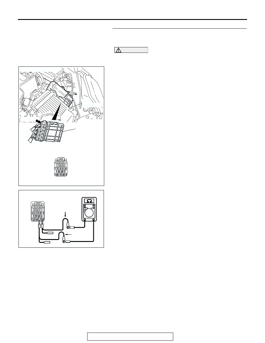
STEP 10. Check the terminator resistor inside the 
powertrain control module. Measure the resistance at 

powertrain control module connector B-19.

CAUTION

A digital multimeter should be used. For details refer to 

P.54C-4

.

(1) Disconnect powertrain control module connector B-19, and 

measure the resistance at the component side of 
powertrain control module connector B-19.

(2) Measure the resistance between powertrain control module 

connector terminals 17 and 18.

OK: 120 

± 20 

Q: Does the resistance measure 120 

± 20 ?

YES : If the resistance measures 120 

± 20 Ω, go to Step 11.

NO :  If the resistance does not measure 120 

± 20 , replace 

the powertrain control module.

AC306248AD

B-19 (B)

CONNECTOR: B-19

PCM

AIR
CLEANER

HARNESS SIDE

AC209438

AC209438

AC209438

AC209438

COMPONENT SIDE: B-19

BD

TEST 
HARNESS

TEST 
HARNESS

DIAGNOSIS

TSB Revision

CONTROLLER AREA NETWORK (CAN)

54C-464

STEP 11. Check the CAN bus lines inside the ABS-ECU. 

Measure the resistance at ABS-ECU connector A-02.

CAUTION

A digital multimeter should be used. For details refer to 

P.54C-4

.

CAUTION

The test wiring harness should be used. For details refer to 

P.54C-4

.

(1) Disconnect ABS-ECU connector A-02, and measure the 

resistance at the component side of ABS-ECU connector 
A-02.

(2) Turn the ignition switch to the "LOCK" (OFF) position.

CAUTION

Disconnect the negative battery terminal. For details refer 
to 

P.54C-4

.

(3) Disconnect the negative battery terminal.

(4) Measure the resistance between ABS-ECU connector 

terminals 7 and 23.

OK: 2 ohms or less

(5) Measure the resistance between ABS-ECU connector 

terminals 24 and 25.

OK: 2 ohms or less

CAUTION

Strictly observe the specified wiring harness repair proce-
dure. For details refer to 

P.54C-5

.

Q: Do all the resistances measure 2 ohms or less?

YES : If the voltage measures 2 V or less, diagnose CAN 

bus lines thoroughly by referring to 

P.54C-571


<Vehicles without multi-center display (middle-grade 
type)> or 

P.54C-584

 <Vehicles with multi-center 

display (middle-grade type)>.

NO :  Replace the ABS-ECU.

AC305206

CONNECTOR: A-02

AG

A-02 (GR)

HARNESS SIDE

AC209438

COMPONENT SIDE: A-02

TEST 
HARNESS

AC

TEST 
HARNESS

AC209438

COMPONENT SIDE: A-02

AD

TEST 
HARNESS

TEST 
HARNESS

DIAGNOSIS

TSB Revision

CONTROLLER AREA NETWORK (CAN)

54C-465

DIAGNOSTIC ITEM 14: Diagnose CAN bus lines thoroughly <Vehicles without ABS and vehicles 
without multi-center display (middle-grade type)>

CAUTION

When servicing a CAN bus line, ground yourself 
by touching a metal object such as an unpainted 
water pipe. If you fail to do so, a component con-
nected to the CAN bus line may be damaged.

DATA LINK
CONNECTOR

ETACS-ECU

POWERTRAIN
CONTROL MODULE

JOINT
CONNECTOR (3)

COMBINATION
METER

A/C-ECU

SRS-ECU

NOTE

: MANUAL AIR CONDITIONING SYSTEM <LOW>
: MANUAL AIR CONDITIONING SYSTEM <MIDDLE>
  OR AUTOMATIC AIR CONDITIONING SYSTEM

DIAGNOSIS

TSB Revision

CONTROLLER AREA NETWORK (CAN)

54C-466

.

TROUBLE JUDGMENT
If the MUT-III cannot received signals from ECUs, 
CAN bus line connector(s) are broken or an open cir-
cuit has occurred.

.

COMMENTS ON TROUBLE SYMPTOM
The wiring harness wire or connectors may have 
loose, corroded, or damage terminals, or terminals 
pushed back in the connector, or a ECU may be 
defective.

.

TROUBLESHOOTING HINTS

• The wiring harness or connectors may have 

loose, corroded, or damage terminals, or termi-
nals pushed back in the connector

• The ETACS-ECU may be defective

• The combination meter may be defective

• The A/C-ECU may be defective

• The SRS-ECU may be defective

• The powertrain control module may be defective

DIAGNOSIS

Required Special Tools:

• MB991223: Harness Set

• MB991958: Scan Tool (MUT-III Sub Assembly)

• MB991824: Vehicle Communication Interface (V.C.I.)

• MB991827: MUT-III USB Cable

• MB991910: MUT-III Main Harness A

AC306248AB

B-19 (B)

CONNECTOR: B-19

AIR
CLEANER

PCM

AC305231BZ

C-101

C-125 (B)

C-29

C-02

CONNECTORS: C-02, C-29, C-101, C-125

AC305233 AU

CONNECTORS: C-10, C-15, C-22, C-121

C-121 (Y)

C-22 (Y)

C-10 (B)

C-15 (B)

AC305413

C-218 (GR)

CONNECTOR: C-218

AJ

JUNCTION BLOCK
(REAR VIEW)


Content   ..  461  462  463  464   ..