Mitsubishi Galant (2004+). Manual - part 447


  Index      Mitsubishi     Mitsubishi Galant - service repair manual 2004 year


Search            


Content   ..  445  446  447  448   ..


Mitsubishi Galant (2004+). Manual - part 447


DIAGNOSIS

TSB Revision

CONTROLLER AREA NETWORK (CAN)

54C-399

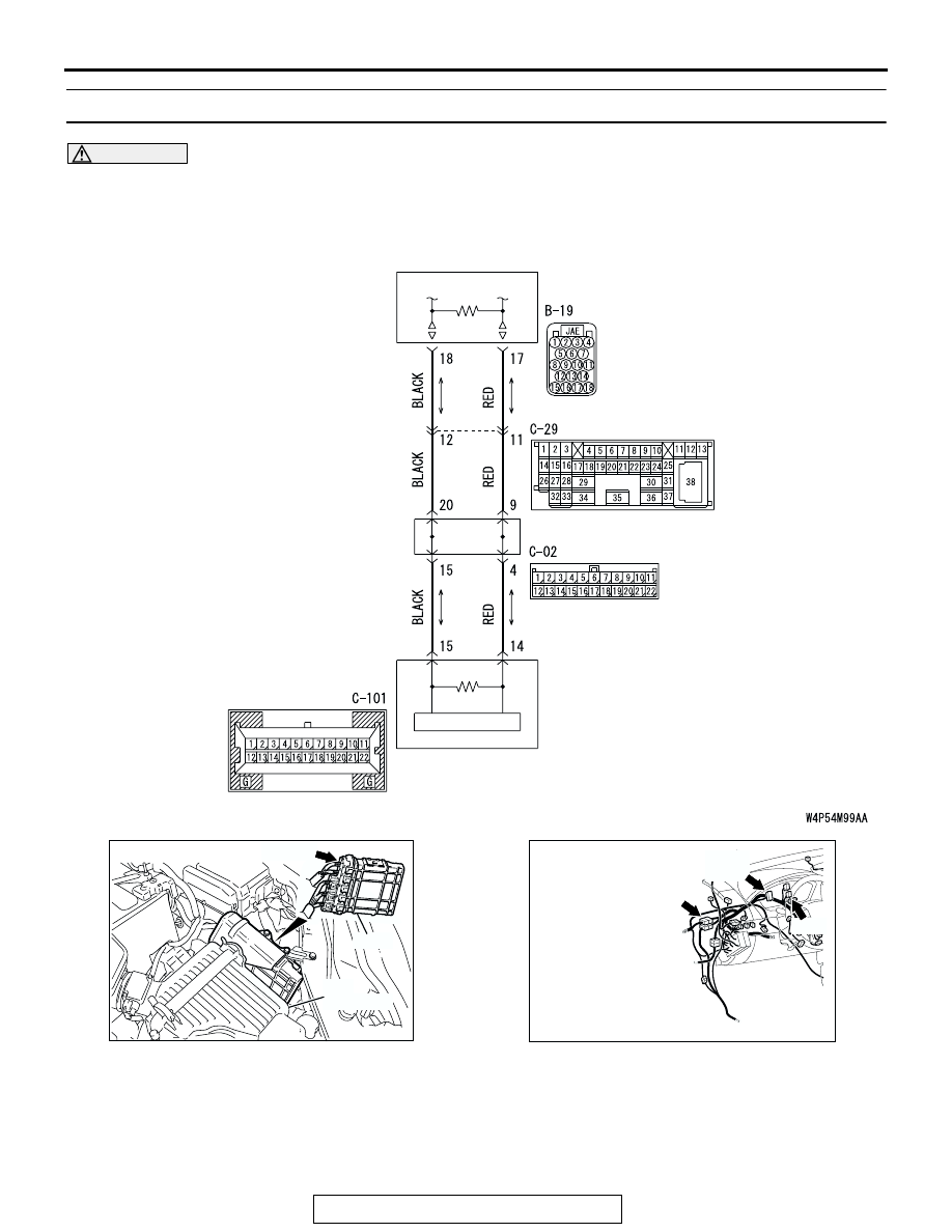
DIAGNOSTIC ITEM 10: Diagnose terminator resistors at both ends <Vehicles without ABS>

CAUTION

When servicing a CAN bus line, ground yourself 
by touching a metal object such as an unpainted 
water pipe. If you fail to do so, a component con-
nected to the CAN bus line may be damaged.

.

POWERTRAIN
CONTROL MODULE

JOINT
CONNECTOR (3)

COMBINATION
METER

AC306248AB

B-19 (B)

CONNECTOR: B-19

AIR
CLEANER

PCM

AC305231CA

C-101

C-29

C-02

CONNECTORS: C-02, C-29, C-101

DIAGNOSIS

TSB Revision

CONTROLLER AREA NETWORK (CAN)

54C-400

TROUBLE JUDGMENT
The terminator resistors at both ends of CAN bus 
lines may be damaged, when the resistance 
between the CAN bus lines (CAN_L and H lines) is 
more than 2 ohms.

.

COMMENTS ON TROUBLE SYMPTOM
The CAN bus line harness wires or connectors may 
be damaged (open circuit may be present on CAN_L 
or CAN_H line between the data link connector and 
CAN main bus lines, or CAN main bus lines may be 
open at both sides), or the combination meter and 
the powertrain control module may be defective. 

.

TROUBLESHOOTING HINTS

• The wiring harness or connectors may have 

loose, corroded, or damaged terminals, or termi-
nals pushed back in the connector

• The combination meter may be defective

• The powertrain control module may be defective

DIAGNOSIS

Required Special Tool:

• MB991223: Harness Set

STEP 1. Check intermediate connector C-29 for loose, 
corroded or damaged terminals, or terminals pushed back 
in the connector.

CAUTION

The strand end of the twisted wire should be within 10 cm 
(4 inches) from the connector. For details refer to 

P.54C-4

.

Q: Is intermediate connector C-29 in good condition?

YES : Go to Step 2.
NO :  Repair the damaged parts.

AC305231AI

CONNECTOR: C-29

DIAGNOSIS

TSB Revision

CONTROLLER AREA NETWORK (CAN)

54C-401

STEP 2. Check the instrument panel wiring harness side 
CAN bus lines (communication line including the 
combination meter). Measure the resistance at 

intermediate connector C-29.

CAUTION

A digital multimeter should be used. For details refer to 

P.54C-4

.

CAUTION

The test wiring harness should be used. For details refer to 

P.54C-4

.

(1) Disconnect intermediate connector C-29, and measure the 

resistance at its female side connector (instrument panel 
wiring harness side).

(2) Turn the ignition switch to the "LOCK" (OFF) position.

CAUTION

Disconnect the negative battery terminal. For details refer 
to 

P.54C-4

.

(3) Disconnect the negative battery terminal.

(4) Measure the resistance between intermediate connector 

terminals 11 and 12.

OK: 120 

± 20 

Q: Does the resistance measure 120 

± 20 ?

YES : If the resistance measures 120 

± 20 Ω, go to Step 8.

NO :  If the resistance does not measure 120 

± 20 Ω, go to 

Step 3 .

AC305231AI

CONNECTOR: C-29

AC204582

AC204582CZ

TEST 
HARNESS

TEST 
HARNESS

FEMALE SIDE: C-29

DIAGNOSIS

TSB Revision

CONTROLLER AREA NETWORK (CAN)

54C-402

STEP 3. Check joint connector (3) C-02 and combination 
meter connector C-101 for loose, corroded or damaged 
terminals, or terminals pushed back in the connector.

CAUTION

The strand end of the twisted wire should be within 10 cm 
(4 inches) from the connector. For details refer to 

P.54C-4

.

Check the joint connector at the wiring harness side for loose, 
corroded or damaged terminals, or terminals pushed back in 
the connector, and also check the short pin behind the connec-
tor for corrosion, deformation and delamination.
Q: Are joint connector (3) C-02 and combination meter 

connector C-101 in good condition?
YES : 
Go to Step 4.
NO :  Repair the damaged parts. Replace the joint 

connector as necessary. Then go to Step 2.

AC305232

HARNESS SIDE

C-101

CONNECTORS: C-02, C-101

AE

C-02

C-02

C-101

AC209350

1

12

2

13

3

14

4

15

5

16

6

17

7

18

8

19

9

20

10

21

11

22

AB

SHORT PIN


Content   ..  445  446  447  448   ..