Mitsubishi Galant (2004+). Manual - part 446


  Index      Mitsubishi     Mitsubishi Galant - service repair manual 2004 year


Search            


Content   ..  444  445  446  447   ..


Mitsubishi Galant (2004+). Manual - part 446


DIAGNOSIS

TSB Revision

CONTROLLER AREA NETWORK (CAN)

54C-395

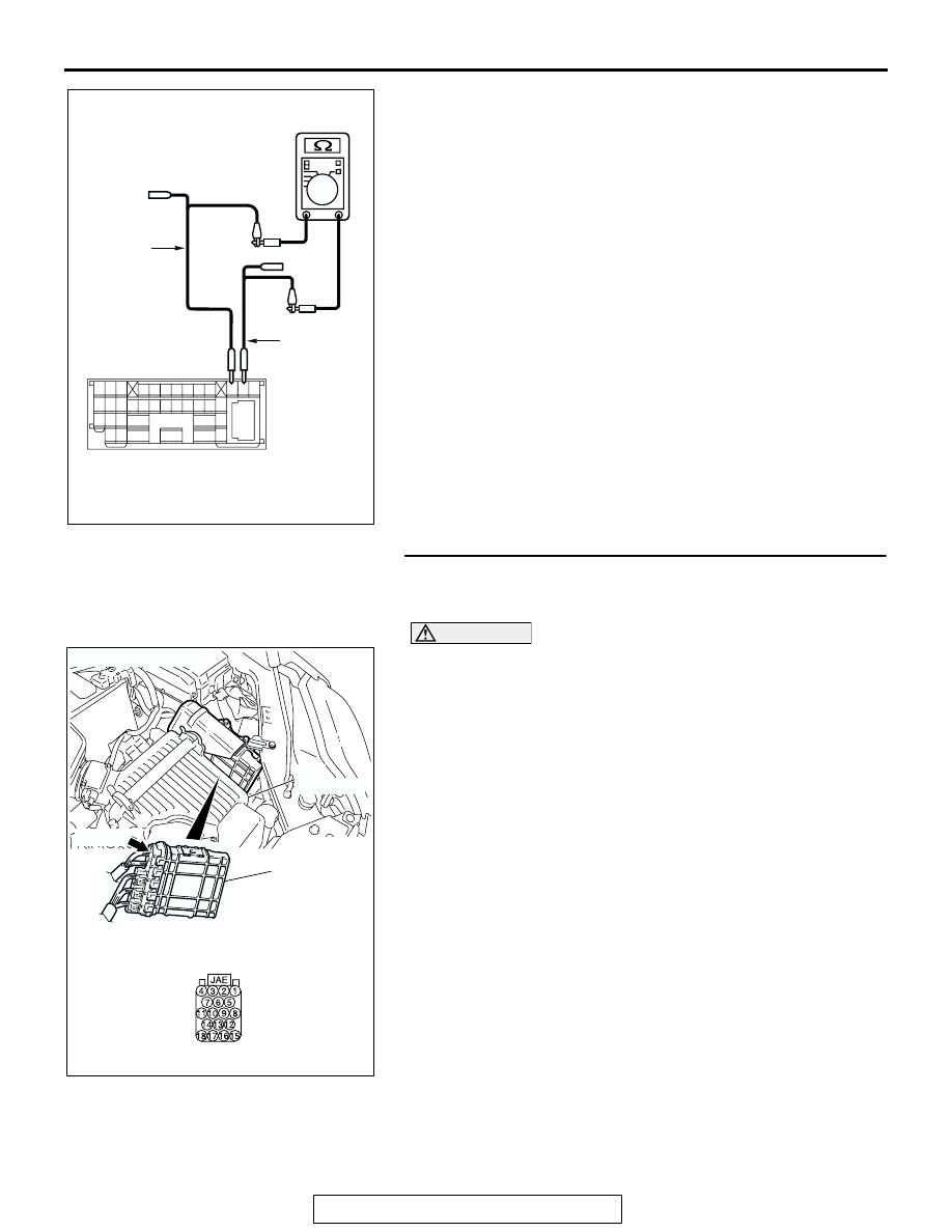
(4) Measure the resistance between intermediate connector 

terminals 11 and 12.

OK: 1 k

 or more

Q: Does the resistance measure 1 k

 or more?

YES : If the resistance measures 1 k

Ω or more, go to Step 

32  .

NO :  If the resistance measures less than 1 k

Ω, repair the 

wiring harness between intermediate connector C-29 
and ABS-ECU connector.

STEP 32. Check powertrain control module connector B-19 
for loose, corroded or damaged terminals, or terminals 
pushed back in the connector.

CAUTION

The strand end of the twisted wire should be within 10 cm 
(4 inches) from the connector. For details refer to 

P.54C-4

.

Q: Is powertrain control module connector B-19 in good 

condition?
YES : 
Go to Step 33.
NO :  Repair the damaged parts.

AC204582

2 3

27

32

28

33

16

15

4 5

19

18

29

17

34

7 8

35

22

21

9 10

30

36

31

37

25

24

23

6

20

1

14

26

11

13

12

38

BX

TEST 
HARNESS

TEST 
HARNESS

MALE SIDE: C-29

AC306248AD

B-19 (B)

CONNECTOR: B-19

PCM

AIR
CLEANER

HARNESS SIDE

DIAGNOSIS

TSB Revision

CONTROLLER AREA NETWORK (CAN)

54C-396

STEP 33. Check the CAN_L and H lines (communication 
lines only) between the powertrain control module 
connector and the ABS-ECU connector for a short circuit. 
Measure the resistance at powertrain control module 

connector B-19.

CAUTION

A digital multimeter should be used. For details refer to 

P.54C-4

.

CAUTION

The test wiring harness should be used. For details refer to 

P.54C-4

.

(1) Disconnect powertrain control module connector B-19 and 

ABS-ECU connector A-02, and measure the resistance at 
the harness side of powertrain control module connector 
B-19.

(2) Turn the ignition switch to the "LOCK" (OFF) position.

CAUTION

Disconnect the negative battery terminal. For details refer 
to 

P.54C-4

.

(3) Disconnect the negative battery terminal.

AC305206

CONNECTOR: A-02

AG

A-02 (GR)

HARNESS SIDE

AC306248AD

B-19 (B)

CONNECTOR: B-19

PCM

AIR
CLEANER

HARNESS SIDE

DIAGNOSIS

TSB Revision

CONTROLLER AREA NETWORK (CAN)

54C-397

(4) Measure the resistance between powertrain control module 

connector terminals 17 and 18.

OK: 1 k

 or more

CAUTION

Strictly observe the specified wiring harness repair proce-
dure. For details refer to 

P.54C-5

.

Q: Does the resistance measure 1 k

 or more?

YES : If the resistance measures 1 k

Ω or more, go to Step 

34  .

NO :  If the resistance measures less than 1 k

Ω, repair the 

wiring harness between powertrain control module 
connector and ABS-ECU connector.

STEP 34. Check the ABS-ECU for short circuit. Measure 

the resistance at ABS-ECU connector A-02.

CAUTION

A digital multimeter should be used. For details refer to 

P.54C-4

.

(1) Disconnect ABS-ECU connector A-02, and measure the 

resistance at the component side of ABS-ECU connector 
A-02.

(2) Measure the resistance between ABS-ECU connector 

terminals 7 and 25.

OK: 1 k

 or more

Q: Does the resistance measure 1 k

 or more?

YES : If the resistance measures 1 k

Ω or more, go to Step 

35  .

NO :  If the resistance measures less than 1 k

Ω, replace the 

ABS-ECU.

AC209438

AC209438

AC209438

HARNESS SIDE: B-19

BC

TEST 
HARNESS

TEST 
HARNESS

AC305206

CONNECTOR: A-02

AG

A-02 (GR)

HARNESS SIDE

AC209438

COMPONENT SIDE: A-02

TEST 
HARNESS

AB

TEST 
HARNESS

DIAGNOSIS

TSB Revision

CONTROLLER AREA NETWORK (CAN)

54C-398

STEP 35. Check the powertrain control module for short 
circuit. Measure the resistance at powertrain control 

module connector B-19.

CAUTION

A digital multimeter should be used. For details refer to 

P.54C-4

.

(1) Disconnect powertrain control module connector B-19, and 

measure the resistance at the component side of 
powertrain control module connector B-19.

(2) Measure the resistance between powertrain control module 

connector terminals 17 and 18.

OK: 120 

± 20 

Q: Does the resistance measure 120 

± 20 ?

YES : If the resistance measures 120 

± 20 Ω, diagnose CAN 

bus lines thoroughly by referring to 

P.54C-534

.

NO :  If the resistance does not measure 120 

± 20 Ω, 

replace the powertrain control module.

AC306248AD

B-19 (B)

CONNECTOR: B-19

PCM

AIR
CLEANER

HARNESS SIDE

AC209438

AC209438

AC209438

AC209438

COMPONENT SIDE: B-19

BD

TEST 
HARNESS

TEST 
HARNESS


Content   ..  444  445  446  447   ..