Mitsubishi Galant (2004+). Manual - part 351
DIAGNOSIS
TSB Revision
CONTROLLER AREA NETWORK (CAN)
54C-15
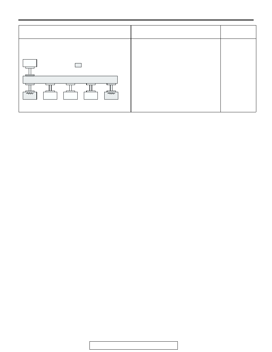
<Comment>
Disconnection in red displayed area is
estimated.
Diagnostic Item 10
Diagnose terminator resistors at both
ends <Vehicles without ABS>
MUT-III SCREEN
DIAGNOSIS DETAILS
REFERENCE
PAGE
AC305790
: Red section on screen
PCM
METER
-ECU
AC
MUT
ETACS
-ECU
AC-ECU
SRS-ECU
J/C