Mitsubishi Galant (2004+). Manual - part 333


  Index      Mitsubishi     Mitsubishi Galant - service repair manual 2004 year


Search            


Content   ..  331  332  333  334   ..


Mitsubishi Galant (2004+). Manual - part 333


INPUT SIGNAL PROCEDURES

TSB Revision

SIMPLIFIED WIRING SYSTEM (SWS)

54B-523

INSPECTION PROCEDURE N-2: ETACS-ECU does not receive any signal from the hazard warning 
light switch.

.

CIRCUIT OPERATION
The ETACS-ECU operates the following functions or 
systems according to signal from the hazard warning 
light switch:

• Turn-signal light buzzer

• Hazard warning light

• Keyless entry system (registering the encrypted 

code)

.

TECHNICAL DESCRIPTION (COMMENT)
If the signal is not normal, the equipment or systems 
described in "CIRCUIT OPERATION" do not work 
normally.

.

TROUBLESHOOTING HINTS

• The hazard warning light switch may be defective

• The wiring harness or connectors may have 

loose, corroded, or damaged terminals, or termi-
nals pushed back in the connector

• The ETACS-ECU may be defective

HAZARD 
WARNING 
LIGHT 
SWITCH

ETACS-ECU

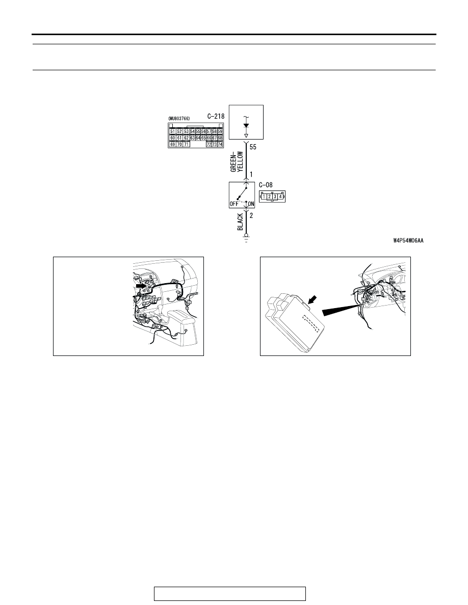
Hazard Warning Light Switch Input Circuit

AC305233AQ

CONNECTOR: C-08

AC305413AL

CONNECTOR: C-218

C-218 (GR)

INPUT SIGNAL PROCEDURES

TSB Revision

SIMPLIFIED WIRING SYSTEM (SWS)

54B-524

DIAGNOSIS

Required Special Tool:

• MB991223: Harness Set

STEP 1. Check hazard warning light switch connector C-08 
for loose, corroded or damaged terminals, or terminals 
pushed back in the connector.

Q: Is hazard warning light switch connector C-08 in good 

condition?
YES : 
Go to Step 2.
NO :  Repair or replace the damaged component(s). Refer 

to GROUP 00E, Harness Connector Inspection 

P.00E-2

. If the equipment described in "CIRCUIT 

OPERATION" work normally, the input signal from the 
hazard warning light switch should be normal.

STEP 2. Check the hazard warning light switch.

Remove the hazard warning light switch. Refer to GROUP 54A, 
Hazard Warning Light Switch 

P.54A-130

. Then check continu-

ity between the switch terminals.

Q: Is the hazard warning light switch in good condition?

YES : Go to Step 3.
NO :  Replace the hazard warning light switch. If the 

equipment described in "CIRCUIT OPERATION", 
work normally the input signal from the hazard 
warning light switch should be normal.

AC305233AS

CONNECTOR: C-08

HARNESS SIDE

SWITCH 
POSITION

TESTER 
CONNECTION

SPECIFIED 
CONDITION

Released

− 2

Open circuit

Pressed

− 2

Less than 2 ohms

AC307450

INPUT SIGNAL PROCEDURES

TSB Revision

SIMPLIFIED WIRING SYSTEM (SWS)

54B-525

STEP 3. Check the ground circuit to the hazard warning 
light switch. Measure the resistance at hazard warning 
light switch connector C-08.

(1) Disconnect hazard warning light switch connector C-08 and 

measure the resistance available at the wiring harness side 
of the connector.

(2) Measure the resistance value between terminal 2 and 

ground.

• The resistance should be 2 ohms or less.

Q: Is the measured resistance 2 ohms or less?

YES : Go to Step 5.
NO :  Go to Step 4.

STEP 4. Check the wiring harness between hazard warning 
light switch connector C-08 (terminal 2) and ground.

Q: Is the wiring harness between hazard warning light 

switch connector C-08 (terminal 2) and ground in good 
condition?
YES : 
No action is necessary and testing is complete.
NO :  The wiring harness may be damaged or the 

connector(s) may have loose, corroded or damaged 
terminals, or terminals pushed back in the connector. 
Repair the wiring harness as necessary. If the 
equipment described in "CIRCUIT OPERATION" work 
normally, the input signal from the hazard warning 
light switch should be normal.

AC305233AS

CONNECTOR: C-08

HARNESS SIDE

AC209364GW

CONNECTOR C-08
(HARNESS SIDE)

AC305233AS

CONNECTOR: C-08

HARNESS SIDE

INPUT SIGNAL PROCEDURES

TSB Revision

SIMPLIFIED WIRING SYSTEM (SWS)

54B-526

STEP 5. Check ETACS-ECU connector C-218 for loose, 
corroded or damaged terminals, or terminals pushed back 
in the connector.

Q: Is ETACS-ECU connector C-218 in good condition?

YES : Go to Step 6.
NO :  Repair or replace the damaged component(s). Refer 

to GROUP 00E, Harness Connector Inspection 

P.00E-2

. If the equipment described in "CIRCUIT 

OPERATION" work normally, the input signal from the 
hazard warning light switch should be normal.

STEP 6. Check the wiring harness between hazard warning 
light switch connector C-08 (terminal 1) and ETACS-ECU 
connector C-218 (terminal 55).

Q: Is the wiring harness between hazard warning light 

switch connector C-08 (terminal 1) and ETACS-ECU 
connector C-218 (terminal 55) in good condition?
YES : 
Replace the ETACS-ECU. If the equipment described 

in "CIRCUIT OPERATION" work normally, the input 
signal from the hazard warning light switch should be 
normal.

NO :  The wiring harness may be damaged or the 

connector(s) may have loose, corroded or damaged 
terminals, or terminals pushed back in the connector. 
Repair the wiring harness as necessary. If the 
equipment described in "CIRCUIT OPERATION" work 
normally, the input signal from the hazard warning 
light switch should be normal.

AC305413AN

CONNECTOR: C-218

JUNCTION BLOCK
(REAR VIEW)

C-218 (GR)

HARNESS SIDE

51

52

53

54

55

56

57

58

59

60

61

62

63

64

65

66

67

68

69

70

71

72

73

74

AC305233AS

CONNECTOR: C-08

HARNESS SIDE

AC305413AN

CONNECTOR: C-218

JUNCTION BLOCK
(REAR VIEW)

C-218 (GR)

HARNESS SIDE

51

52

53

54

55

56

57

58

59

60

61

62

63

64

65

66

67

68

69

70

71

72

73

74


Content   ..  331  332  333  334   ..