Mitsubishi Galant (2004+). Manual - part 325


  Index      Mitsubishi     Mitsubishi Galant - service repair manual 2004 year


Search            


Content   ..  323  324  325  326   ..


Mitsubishi Galant (2004+). Manual - part 325


INPUT SIGNAL PROCEDURES

TSB Revision

SIMPLIFIED WIRING SYSTEM (SWS)

54B-491

DIAGNOSIS

Required Special Tool:

• MB991223: Harness Set

STEP 1. Check ETACS-ECU connector C-219 for loose, 
corroded or damaged terminals, or terminals pushed back 
in the connector.

Q: Is ETACS-ECU connector C-219 in good condition?

YES : Go to Step 2.
NO :  Repair or replace the damaged component(s). Refer 

to GROUP 00E, Harness Connector Inspection 

P.00E-2

. If the functions described in "CIRCUIT 

OPERATION" work normally, the input signal from the 
ignition switch (IG1) should be normal.

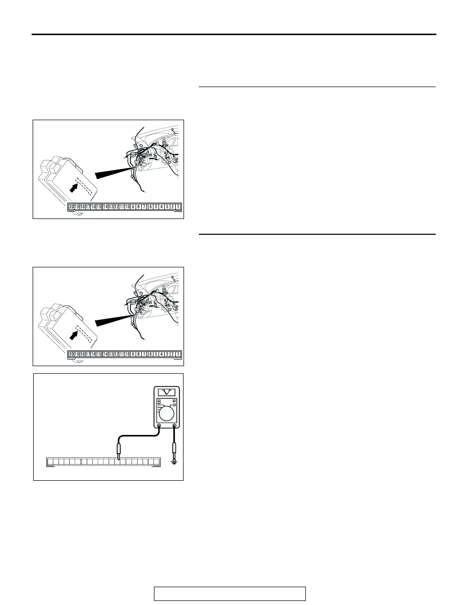
STEP 2. Check the ignition switch (IG1) line of the power 
supply circuit to the ETACS-ECU. Measure the voltage at 
ETACS-ECU connector C-219.

(1) Disconnect ETACS-ECU connector C-219 and measure the 

voltage available at the junction block side of the connector. 

(2) Turn the ignition switch to the "ON" position.

(3) Measure the voltage between terminal 8 and ground.

• The voltage should measure approximately 12 volts 

(battery positive voltage).

Q: Is the measured voltage approximately 12 volts (battery 

positive voltage)?
YES : 
Replace the ETACS-ECU. If the functions described 

in "CIRCUIT OPERATION" work normally, the input 
signal from the ignition switch (IG1) should be normal.

NO :  Go to Step 3.

AC305413 AG

CONNECTOR: C-219

JUNCTION BLOCK SIDE

JUNCTION BLOCK

(REAR VIEW)

AC305413 AG

CONNECTOR: C-219

JUNCTION BLOCK SIDE

JUNCTION BLOCK

(REAR VIEW)

AC209799

2019 18 1716 15 14 13 12 11 10 9 8 7 6 5 4 3 2 1

AB

CONNECTOR C-219
(JUNCTION BLOCK SIDE)

INPUT SIGNAL PROCEDURES

TSB Revision

SIMPLIFIED WIRING SYSTEM (SWS)

54B-492

STEP 3. Check the wiring harness between ETACS-ECU 
connector C-219 (terminal 8) and the ignition switch (IG1).

NOTE: Also check junction block connector C-215 for loose, 
corroded, or damaged terminals, or terminals pushed back in 
the connector. If junction block connector C-215 is damaged, 
repair or replace the damaged component(s) as described in 
GROUP 00E, Harness Connector Inspection 

P.00E-2

Q: Is the wiring harness between ETACS-ECU connector 

C-219 (terminal 8) and ignition switch (IG1) in good 
condition?
YES : 
No action is necessary and testing is complete.
NO :  The wiring harness may be damaged or the 

connector(s) may have loose, corroded or damaged 
terminals, or terminals pushed back in the connector. 
Repair the wiring harness as necessary. If the 
functions described in "CIRCUIT OPERATION" work 
normally, the input signal from the ignition switch 
(IG1) should be normal.

AC305413 AG

CONNECTOR: C-219

JUNCTION BLOCK SIDE

JUNCTION BLOCK

(REAR VIEW)

AC305415

HARNESS SIDE

JUNCTION BLOCK
(FRONT VIEW)

CONNECTOR: C-215

AV

INPUT SIGNAL PROCEDURES

TSB Revision

SIMPLIFIED WIRING SYSTEM (SWS)

54B-493

INSPECTION PROCEDURE M-3: ETACS-ECU does not receive any signal from the fog light switch.

.

CIRCUIT OPERATION
The ETACS-ECU operates the fog lights according to 
signal from the fog light switch.

.

TECHNICAL DESCRIPTION (COMMENT)
If the signal is not normal, the fog lights do not work 
normally. If the signal is not normal, the fog light 
switch or the ETACS-ECU may be defective.

.

TROUBLESHOOTING HINTS

• The fog light switch may be defective

• The wiring harness or connectors may have 

loose, corroded, or damaged terminals, or termi-
nals pushed back in the connector

• The ETACS-ECU may be defective

FOG LIGHT 
SWITCH

ETACS-ECU

Fog Light Switch Input Circuit

AC305231

CONNECTOR: C-128

BB

AC305413AL

CONNECTOR: C-218

C-218 (GR)

INPUT SIGNAL PROCEDURES

TSB Revision

SIMPLIFIED WIRING SYSTEM (SWS)

54B-494

DIAGNOSIS

Required Special Tool:

• MB991223: Harness Set

STEP 1. Check fog light switch connector C-128 for loose, 
corroded or damaged terminals, or terminals pushed back 
in the connector.

Q: Is fog light switch connector C-128 in good condition?

YES : Go to Step 2.
NO :  Repair or replace the damaged component(s). Refer 

to GROUP 00E, Harness Connector Inspection 

P.00E-2

. Repair the fog light switch. If the fog light 

switch operates normally, a correct signal is sent from 
the fog light switch.

STEP 2. Check the fog light switch.

Remove the fog light switch. Refer to GROUP 54A, Fog light 

P.54A-130

. Then check continuity between the switch termi-

nals.

Q: Is the fog light switch in good condition?

YES : Go to Step 3.
NO :  Repair the fog light switch. If the fog light switch 

operates normally, a correct signal is sent from the 
fog light switch.

AC305231

AC305231

HARNESS SIDE

CONNECTOR: C-128

BS

SWITCH 
POSITION

TESTER 
CONNECTION

SPECIFIED 
CONDITION

Released

− 2

Open circuit

Pressed

− 2

Less than 2 ohms

AC205430

AB

6

5

3

2

4

1


Content   ..  323  324  325  326   ..