Mitsubishi Galant (2004+). Manual - part 256


  Index      Mitsubishi     Mitsubishi Galant - service repair manual 2004 year


Search            


Content   ..  254  255  256  257   ..


Mitsubishi Galant (2004+). Manual - part 256


SYMPTOM PROCEDURES

TSB Revision

SIMPLIFIED WIRING SYSTEM (SWS)

54B-215

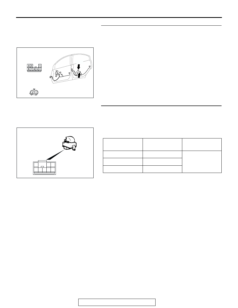
STEP 23. Check rear power window sub switch (RH) 
connector E-06 and rear power window regulator motor 
(RH) connector E-07 for loose, corroded or damaged 
terminals, or terminals pushed back in the connector.

Q: Are rear power window sub switch (RH) connector E-06 

and rear power window regulator motor (RH) connector 
E-07 in good condition?
YES : 
Go to Step 24.
NO :  Repair or replace the damaged component(s). Refer 

to GROUP 00E, Harness Connector Inspection 

P.00E-2

. When the rear power window sub switch 

(RH) is operated, the rear power window (RH) should 
raise and lower normally.

STEP 24. Check the rear power window sub switch (RH) for 
continuity.
(1) Remove the rear power window sub switch (RH). Refer to 

GROUP 42, Door, Door Glass and Regulator 

P.42-39

.

(2) Check continuity when the rear power window sub switch 

(RH) is operated to "UP" or "DOWN" position.

Q: Is the rear power window sub switch (RH) normal?

YES : Go to Step 25.
NO :  Replace the rear power window sub switch (RH). 

When the rear power window sub switch (RH) is 
operated, the rear power window (RH) should raise 
and lower normally.

AC305333

AD

HARNESS SIDE

CONNECTOR:E-06,E-07

E-06

E-07

E-06

E-07(GR)

HARNESS SIDE

SWITCH 
POSITION

TESTER 
CONNECTION

SPECIFIED 
CONDITION

UP

− 5, 6 − 7

Less than 2 ohms

OFF

− 5, 7 − 8

DOWN

− 6, 7 − 8

AC210747

8

3

1

4 5 6

2

7

AB

<REAR>

SYMPTOM PROCEDURES

TSB Revision

SIMPLIFIED WIRING SYSTEM (SWS)

54B-216

STEP 25. Check the rear power window regulator motor 
(RH).

(1) Remove the rear power window regulator assembly (RH). 

Refer to GROUP 42, Door, Door Glass and Regulator 

P.42-39

.

(2) Connect a battery to the motor terminal, and check that the 

motor runs freely.

Q: Is the rear power window regulator motor (RH) normal?

YES : Go to Step 26.
NO :  Replace the rear power regulator assembly (RH). 

When the rear power window sub switch (RH) is 
operated, the rear power window (RH) should raise 
and lower normally.

STEP 26. Check the battery power supply circuit to the rear 
power window sub switch (RH). Measure the voltage at 
rear power window sub switch (RH) connector E-06.

(1) Disconnect rear power window sub switch (RH) connector 

E-06 and measure the voltage available at the wiring 

harness side of the connector.

(2) Measure the voltage between terminal 6 and ground.

• The voltage should measure approximately 12 volts 

(battery positive voltage).

Q: Is the measured voltage approximately 12 volts (battery 

positive voltage)?
YES : 
Go to Step 29.
NO :  Go to Step 27.

BATTERY CONNECTION

SLIDER POSITION

• Connect terminal 1 to the 

negative battery terminal

• Connect terminal 2 to the 

positive battery terminal

UP

• Connect terminal 2 to the 

negative battery terminal

• Connect terminal 1 to the 

positive battery terminal

DOWN

1 2

AC206013AB

AC305333

CONNECTOR:E-06

HARNESS SIDE

AE

AC209365EJ

CONNECTOR E-06
(HARNESS SIDE)

SYMPTOM PROCEDURES

TSB Revision

SIMPLIFIED WIRING SYSTEM (SWS)

54B-217

STEP 27. Check power window relay connector C-203 for 
loose, corroded or damaged terminals, or terminals 
pushed back in the connector.

Q: Is power window relay connector C-203 in good 

condition?
YES : 
Go to Step 28.
NO :  Repair or replace the damaged component(s). Refer 

to GROUP 00E, Harness Connector Inspection 

P.00E-2

. When the rear power window sub switch 

(RH) is operated, the rear power window (RH) should 
raise and lower normally.

STEP 28. Check the wiring harness between power 
window relay connector C-203 (terminal 4) and rear power 

window sub switch (RH) connector E-06 (terminal 6).

AC305415 AC

JUNCTION BLOCK SIDE

CONNECTOR:C-203

JUNCTION BLOCK

(FRONT VIEW)

AC305416

JUNCTION BLOCK SIDE

C-203

HARNESS SIDE

C-215

CONNECTORS: C-203,C-215

AE

C-203

C-215

JUNCTION BLOCK

(FRONT VIEW)

AC305333

CONNECTOR:E-06

HARNESS SIDE

AE

SYMPTOM PROCEDURES

TSB Revision

SIMPLIFIED WIRING SYSTEM (SWS)

54B-218

NOTE: Also check junction block connector C-215, intermedi-
ate connectors C-28 and D-36. If junction block connector 
C-215, intermediate connector C-28 or D-36 is damaged, repair 
or replace the connector as described in GROUP 00E, Harness 
Connector Inspection 

P.00E-2

.

Q: Is the wiring harness between power window relay 

connector C-203 (terminal 4) and rear power window 
sub switch (RH) connector E-06 (terminal 6) in good 
condition?
YES : 
No action is necessary and testing is complete.
NO :  The wiring harness may be damaged or the 

connector(s) may have loose, corroded or damaged 
terminals, or terminals pushed back in the connector. 
Repair the wiring harness as necessary. When the 
rear power window sub switch (RH) is operated, the 
rear power window (RH) should raise and lower 
normally.

STEP 29. Check the ground circuit to the rear power 
window sub switch (RH). Measure the resistance at rear 
power window sub switch (RH) connector E-06.

(1) Disconnect rear power window sub switch (RH) connector 

E-06 and measure the resistance available at the wiring 

harness side of the connector.

(2) Measure the resistance value between terminal 5 and 

ground, and also between terminal 8 and ground.

• The resistance should be 2 ohms or less.

Q: Is the measured resistance 2 ohms or less?

YES : Go to Step 31.
NO :  Go to Step 30.

AC305231AE

CONNECTOR:C-28

AC305264

AB

CONNECTOR: D-36

AC305333

CONNECTOR:E-06

HARNESS SIDE

AE

AC209364FY

CONNECTOR E-06
(HARNESS SIDE)


Content   ..  254  255  256  257   ..