Mitsubishi Galant (2004+). Manual - part 241


  Index      Mitsubishi     Mitsubishi Galant - service repair manual 2004 year


Search            


Content   ..  239  240  241  242   ..


Mitsubishi Galant (2004+). Manual - part 241


SYMPTOM PROCEDURES

TSB Revision

SIMPLIFIED WIRING SYSTEM (SWS)

54B-155

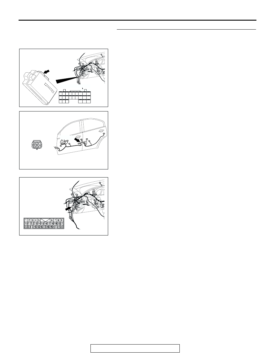
STEP 5. Check the wiring harness between ETACS-ECU 
connector C-217 (terminal 22) and front door lock actuator 
(LH) connector E-15 (terminal 4).

NOTE: Also check intermediate connector C-26 for loose, cor-
roded, or damaged terminals, or terminals pushed back in the 
connector. If intermediate connector C-26 is damaged, repair or 
replace the damaged component(s) as described in GROUP 
00E, Harness Connector Inspection 

P.00E-2

.

Q: Is the wiring harness between ETACS-ECU connector 

C-217 (terminal 22) and front door lock actuator (LH) 
connector E-15 (terminal 4) in good condition?
YES : 
Go to Step 6.
NO :  The wiring harness may be damaged or the 

connector(s) may have loose, corroded or damaged 
terminals, or terminals pushed back in the connector. 
Repair or replace the damaged component(s). Verify 
that the central door locking system works normally.

AC305413AH

CONNECTOR: C-217

HARNESS SIDE

25

26

27

28

29

21

22

23

24

30

31

32

33

34

35

36

37

38

39

40

41

42

43

44

JUNCTION BLOCK

(REAR VIEW)

AC305262

E-15 (B)

HARNESS SIDE

CONNECTOR: E-15

AH

AC305231

CONNECTOR: C-26

AK

SYMPTOM PROCEDURES

TSB Revision

SIMPLIFIED WIRING SYSTEM (SWS)

54B-156

STEP 6. Check the wiring harness between ETACS-ECU 
connector C-219 (terminal 12) and front door lock actuator 
(LH) connector E-15 (terminal 6).

NOTE: Also check intermediate connector C-26 and junction 
block connector C-211 for loose, corroded, or damaged termi-
nals, or terminals pushed back in the connector. If intermediate 
connector C-26 or junction block connector C-211 is damaged, 
repair or replace the damaged component(s) as described in 
GROUP 00E, Harness Connector Inspection 

P.00E-2

.

Q: Is the wiring harness between ETACS-ECU connector 

C-219 (terminal 12) and front door lock actuator (LH) 
connector E-15 (terminal 6) in good condition?
YES : 
Replace the ETACS-ECU. Verify that all the doors 

can be locked and unlocked normally.

NO :  The wiring harness may be damaged or the 

connector(s) may have loose, corroded or damaged 
terminals, or terminals pushed back in the connector. 
Repair or replace the damaged component(s). Verify 
that the central door locking system works normally.

AC305413 AG

CONNECTOR: C-219

JUNCTION BLOCK SIDE

JUNCTION BLOCK

(REAR VIEW)

AC305262

E-15 (B)

HARNESS SIDE

CONNECTOR: E-15

AH

AC305231

CONNECTOR: C-26

AK

AC305415AH

CONNECTOR: C-211

C-211

HARNESS SIDE

JUNCTION BLOCK

(FRONT VIEW)

SYMPTOM PROCEDURES

TSB Revision

SIMPLIFIED WIRING SYSTEM (SWS)

54B-157

STEP 7. Check front door lock actuator (RH) connector 
E-05 for loose, corroded or damaged terminals, or 
terminals pushed back in the connector.

Q: Is front door lock actuator (RH) connector E-05 in good 

condition?
YES : 
Go to Step 8.
NO :  Repair or replace the damaged component(s). Refer 

to GROUP 00E, Harness Connector Inspection 

P.00E-2

. Verify that all the doors can be locked and 

unlocked normally.

STEP 8. Check the front door lock actuator (RH).

Remove the front door lock actuator (RH). The illustration 
shows when the door lock actuator is viewed from inside the 
door. Refer to GROUP 42 

− Door Handle and Latch 

P.42-46

.

Q: Is the front door lock actuator (RH) normal?

YES : Go to Step 9.
NO :  Replace the front door lock actuator (RH). Verify that 

all the doors can be locked and unlocked normally.

AC305333

AH

CONNECTOR: E-05

E-05 (B)

HARNESS SIDE

LEVER 
POSITION

BATTERY 
CONNECTION

LEVER 
OPERATION

At the "LOCK" 
position

• Connect terminal 4 

to the negative 
battery terminal

• Connect terminal 6 

to the positive 
battery terminal

The lever moves 
from the "LOCK" 
position to the 
"UNLOCK" 
position.

At the 
"UNLOCK" 
position

• Connect terminal 6 

to the negative 
battery terminal

• Connect terminal 4 

to the positive 
battery terminal

The lever moves 
from the 
"UNLOCK" position 
to the "LOCK" 
position.

AC210905

1 2 3
4 5 6

VIEW A

B

LOCK

LEVER

UNLOCK

AB

SYMPTOM PROCEDURES

TSB Revision

SIMPLIFIED WIRING SYSTEM (SWS)

54B-158

STEP 9. Check ETACS-ECU connector C-219 for loose, 
corroded or damaged terminals, or terminals pushed back 
in the connector.

Q: Is ETACS-ECU connector C-219 in good condition?

YES : Go to Step 10.
NO :  Repair or replace the damaged component(s). Refer 

to GROUP 00E, Harness Connector Inspection 

P.00E-2

. Verify that all the doors can be locked and 

unlocked normally.

STEP 10. Check the wiring harness between ETACS-ECU 
connector C-219 (terminals 12 and 13) and front door lock 

actuator (RH) connector E-05 (terminals 4 and 6).

AC305413 AG

CONNECTOR: C-219

JUNCTION BLOCK SIDE

JUNCTION BLOCK

(REAR VIEW)

AC305413 AG

CONNECTOR: C-219

JUNCTION BLOCK SIDE

JUNCTION BLOCK

(REAR VIEW)

AC305333

AH

CONNECTOR: E-05

E-05 (B)

HARNESS SIDE


Content   ..  239  240  241  242   ..