Mitsubishi Galant (2004+). Manual - part 240


  Index      Mitsubishi     Mitsubishi Galant - service repair manual 2004 year


Search            


Content   ..  238  239  240  241   ..


Mitsubishi Galant (2004+). Manual - part 240


SYMPTOM PROCEDURES

TSB Revision

SIMPLIFIED WIRING SYSTEM (SWS)

54B-151

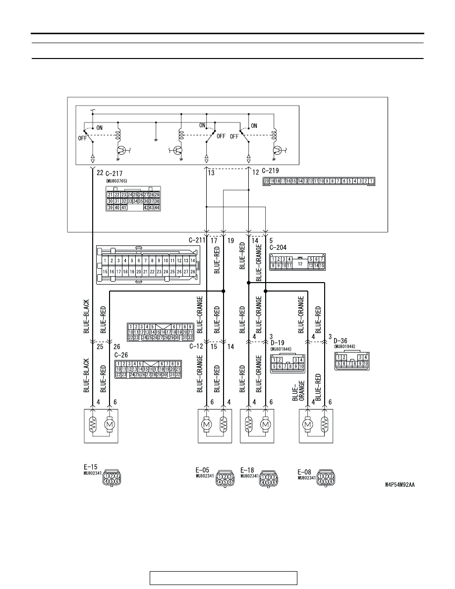
INSPECTION PROCEDURE C-2: Central Door Locking System: Some Doors do not Lock or Unlock.

JUNCTION BLOCK

FRONT DOOR 
LOCK 
ACTUATOR (LH)

FRONT DOOR 
LOCK 
ACTUATOR (RH)

REAR DOOR 
LOCK 
ACTUATOR (LH)

REAR DOOR 
LOCK 
ACTUATOR (RH)

ETACS-ECU

JUNCTION BLOCK SIDE

Central Door Lock Circuit

SYMPTOM PROCEDURES

TSB Revision

SIMPLIFIED WIRING SYSTEM (SWS)

54B-152

.

CIRCUIT OPERATION

• The ETACS-ECU operates the central door lock 

system according to the following signals:

• Front door lock actuator switch

• Door lock key cylinder switch

• Door lock switch, which is incorporated in the 

power window main switch or front power win-
dow sub switch

• The ETACS-ECU locks or unlocks all the doors 

(except liftgate and glass hatch lock) by operating 
the central door lock relay (incorporated in the 
ECU) in response to input signals.

.

AC305233

CONNECTOR: C-12

AE

AC305231

CONNECTOR: C-26

AL

AC305415

C-211

CONNECTORS: C-204, C-211

AI

JUNCTION BLOCK

(FRONT VIEW)

C-204

AC305413

C-219

C-217

CONNECTORS: C-217, C-219

AF

JUNCTION BLOCK

(REAR VIEW)

AC305268

AB

CONNECTOR: D-19

AC305264

CONNECTOR: D-36

AD

AC305333

AF

CONNECTORS: E-05, E-08

E-05 (B)

E-08 (B)

AC305262

AK

CONNECOTRS: E-15, E-18

E-15 (B)

E-18 (B)

SYMPTOM PROCEDURES

TSB Revision

SIMPLIFIED WIRING SYSTEM (SWS)

54B-153

TECHNICAL DESCRIPTION (COMMENT)
The wiring harness between the door lock actuator or 
the ETACS-ECU and the door lock actuator may be 
defective.

.

TROUBLESHOOTING HINTS

• The front door lock actuator or rear door lock 

actuator may be defective

• The wiring harness or connectors may have 

loose, corroded, or damaged terminals, or termi-
nals pushed back in the connector

• The ETACS-ECU may be defective

DIAGNOSIS

Required Special Tool:

• MB991223: Harness Set

STEP 1. Check which door lock is defective.
Q: Which of the door locks is defective?

Driver's door : Go to Step 2.
Front passenger's door : Go to Step 7.
Rear door (LH) : Go to Step 11.
Rear door (RH) : Go to Step 15.

STEP 2. Check front door lock actuator (LH) connector 
E-15 for loose, corroded or damaged terminals, or 
terminals pushed back in the connector.

Q: Is front door lock actuator (LH) connector E-15 in good 

condition?
YES : 
Go to Step 3.
NO :  Repair or check the connector. Refer to GROUP 00E, 

Harness Connector Inspection 

P.00E-2

Verify that all 

the doors can be locked and unlocked normally.

AC305262

E-15 (B)

HARNESS SIDE

CONNECTOR: E-15

AH

SYMPTOM PROCEDURES

TSB Revision

SIMPLIFIED WIRING SYSTEM (SWS)

54B-154

STEP 3. Check the front door lock actuator (LH).

Remove the front door lock actuator (LH). The illustration 
shows when the door lock actuator is viewed from inside the 
door. Refer to GROUP 42 

− Door Handle and Latch 

P.42-46

.

Q: Does the front door lock actuator (LH) work normally?

YES : Go to Step 4.
NO :  Replace the front door lock actuator (LH). Verify that 

all the doors can be locked and unlocked normally.

STEP 4. Check ETACS-ECU connectors C-217 and C-219 
for loose, corroded or damaged terminals, or terminals 
pushed back in the connector.

Q: Are ETACS-ECU connectors C-217 and C-219 in good 

condition?
YES : 
Go to Step 5.
NO :  Repair or check the connector. Refer to GROUP 00E, 

Harness Connector Inspection 

P.00E-2

Verify that all 

the doors can be locked and unlocked normally.

LEVER 
POSITION

BATTERY 
CONNECTION

LEVER 
OPERATION

At the "LOCK" 
position

• Connect terminal 6 

to the negative 
battery terminal

• Connect terminal 4 

to the positive 
battery terminal

The lever moves 
from the "LOCK" 
position to the 
"UNLOCK" 
position.

At the 
"UNLOCK" 
position

• Connect terminal 4 

to the negative 
battery terminal

• Connect terminal 6 

to the positive 
battery terminal

The lever moves 
from the "UNLOCK" 
position to the 
"LOCK" position.

1 2 3
4 5 6

AC210903 AB

VIEW A

A

LOCK

UNLOCK

LEVER

AC305414

CONNECTORS: C-217, C-219

JUNCTION BLOCK 
(REAR VIEW)

C-217

C-219

HARNESS SIDE

C-217

C-219

JUNCTION BLOCK SIDE

21

22

23

24

25

26

27

28

29

38 37 36 3534 33 32 31 30

39

40

41

42

43

44

AB


Content   ..  238  239  240  241   ..