Mitsubishi Galant (2004+). Manual - part 181


  Index      Mitsubishi     Mitsubishi Galant - service repair manual 2004 year


Search            


Content   ..  179  180  181  182   ..


Mitsubishi Galant (2004+). Manual - part 181


AUTO-CRUISE CONTROL

TSB Revision

ENGINE AND EMISSION CONTROL

17-15

DIAGNOSTIC TROUBLE CODE CHART

M1172002200295

Check according to the inspection chart that is 
appropriate for the diagnostic trouble code.

DIAGNOSTIC TROUBLE CODE PROCEDURES

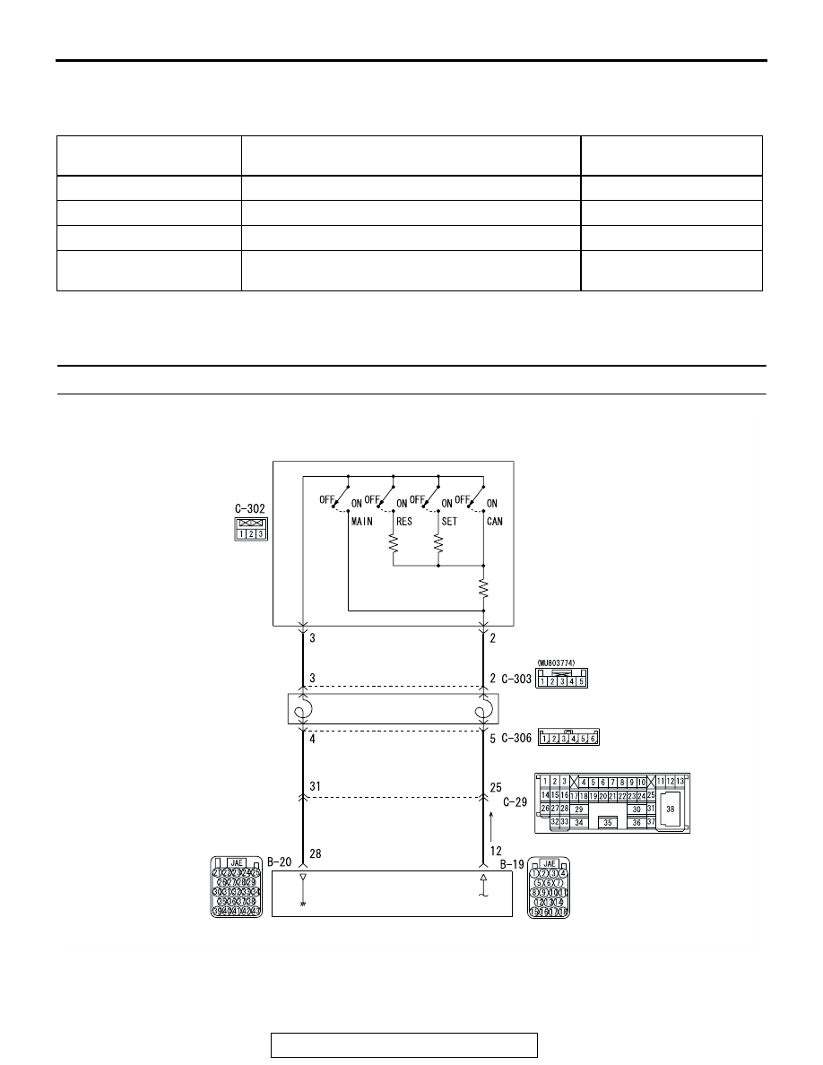
DTC15 : Auto-cruise Control Switch System

DIAGNOSTIC TROUBLE 
CODE NO.

INSPECTION ITEM

REFERENCE PAGE

15

Auto-cruise control switch system

P.17-15

21

Cancel latch signal system

P.17-33

22

Stoplight switch system

P.17-34

23

Powertrain control module (PCM) and its related 
components

P.17-52

AC305709

AUTO-CRUISE
CONTROL
SWITCH

CLOCK
SPRING

POWERTRAIN CONTROL MODULE (PCM)

BLACK

BLACK-

WHITE

BLACK-

RED 

BLACK-

RED 

PINK-

BLACK

PINK-

BLACK

AB

Auto-cruise Control Switch System Circuit

AUTO-CRUISE CONTROL

TSB Revision

ENGINE AND EMISSION CONTROL

17-16

.

CIRCUIT OPERATION
This circuit judges the signals of each switch 
("COAST/SET", "ACC/RES" and "CANCEL") of the 
auto-cruise control switch. The PCM detects the 
state of the auto-cruise control switch by sensing the 
voltages shown below.

• When all switches are OFF: 4.7 − 5.0 volts

• When the "CRUISE" (MAIN) switch is "ON": 0 − 

0.3 volt 

• When the "COAST/SET" switch is ON: 2.0 − 2.8 

volts 

• When the "ACC/RES" switch is ON: 3.3 − 4.1 

volts 

• When the "CANCEL" switch is ON: 0.8 − 1.5 volts 

.

AC305710

B-20 HARNESS

CONNECTOR:

COMPONENT SIDE

B-19 HARNESS

CONNECTOR:

COMPONENT SIDE

AB

B-19 (B)

B-20

CONNECTORS: B-19, B-20

AIR CLEANER

PCM

AC305232

C-29

CONNECTOR: C-29

AC

C-29 MALE SIDE CONNECTOR

AC305236

C-306 HARNESS

CONNECTOR:

COMPONENT SIDE

C-303 HARNESS

CONNECTOR:

COMPONENT SIDE

C-302 HARNESS

CONNECTOR:

COMPONENT SIDE

AB

C-302 (Y)

C-303 (GR)

C-306

CONNECTORS: C-302, C-303, C-306

CLOCK

SPRING

AUTO-CRUISE CONTROL

TSB Revision

ENGINE AND EMISSION CONTROL

17-17

DTC SET CONDITIONS

Check Condition

• The "CRUISE" indicator light illuminates.

Judgement Criteria

• If the auto-cruise control switch is operated, this 

DTC will be set when the PCM terminal voltage is 
different from the standard value.

.

TROUBLESHOOTING HINTS (The most likely 
causes for this case:)

• Malfunction of the auto-cruise control switch.

• Malfunction of the clock spring.

• Damaged harness or connector.

• Malfunction of the PCM.

DIAGNOSIS

Required Special Tools:

• MB991223: Harness set

• MB991923: Power plant ECU check harness

• MB991958: Scan tool (MUT-III sub assembly)

• MB991824: V.C.I.

• MB991827: MUT-III USB cable

• MB991910: MUT-III main harness A

AUTO-CRUISE CONTROL

TSB Revision

ENGINE AND EMISSION CONTROL

17-18

STEP 1. Using scan tool MB991958, check data list item 01: 
Main Switch, list item 02: Set Switch, item 03: Resume 
Switch and list item 04: Cancel Switch.

CAUTION

To prevent damage to scan tool MB991958, always turn the 
ignition switch to the "LOCK" (OFF) position before con-
necting or disconnecting scan tool MB991958. 
(1) Connect scan tool MB991958 to the data link connector. 

(Refer to 

P.17-12

).

(2) Turn the ignition switch to the "ON" position.
(3) Set scan tool MB991958 to data reading mode.

• Auto-cruise control system item 01: Main Switch.

• When "CRUISE" (MAIN) switch is at the "ON" posi-

tion, the display on scan tool MB991958 should be 
"ON".

• When ""CRUISE" (MAIN) switch is at the "OFF" 

position, the display on scan tool MB991958 should 
be "OFF".

(4) Set scan tool MB991958 to data reading mode.

• Auto-cruise control system item 02: Set Switch.

• When "COAST/SET" switch is at the "ON" position, 

the display on scan tool MB991958 should be "ON".

• When "COAST/SET" switch is at the "OFF" position, 

the display on scan tool MB991958 should be 
"OFF".

(5) Set scan tool MB991958 to data reading mode.

• Auto-cruise control system item 03: Resume Switch.

• When "ACC/RES" switch is at the "ON" position, the 

display on scan tool MB991958 should be "ON".

• When "ACC/RES" switch is at the "OFF" position, 

the display on scan tool MB991958 should be 
"OFF".

(6) Set scan tool MB991958 to data reading mode.

• Auto-cruise control system item 04: Cancel Switch.

• When "CANCEL" switch is at the "ON" position, the 

display on scan tool MB991958 should be "ON".

• When "ACC/RES" switch is at the "OFF" position, 

the display on scan tool MB991958 should be 
"OFF".

(7) Turn the ignition switch to the "LOCK" (OFF) position.
(8) Disconnect scan tool MB991958.
Q: Is the switch operating properly?

YES : Go to Step 17 .
NO :  Go to Step 2 .

AC305412

AB

MB991910

DATA LINK

CONNECTOR

MB991824

MB991827


Content   ..  179  180  181  182   ..