Mitsubishi Galant (2004+). Manual - part 1667


  Index      Mitsubishi     Mitsubishi Galant - service repair manual 2004 year


Search            


Content   ..  1665  1666  1667  1668   ..


Mitsubishi Galant (2004+). Manual - part 1667


FUEL TANK

TSB Revision

FUEL SUPPLY

13C-15

INSTALLATION SERVICE POINS

.

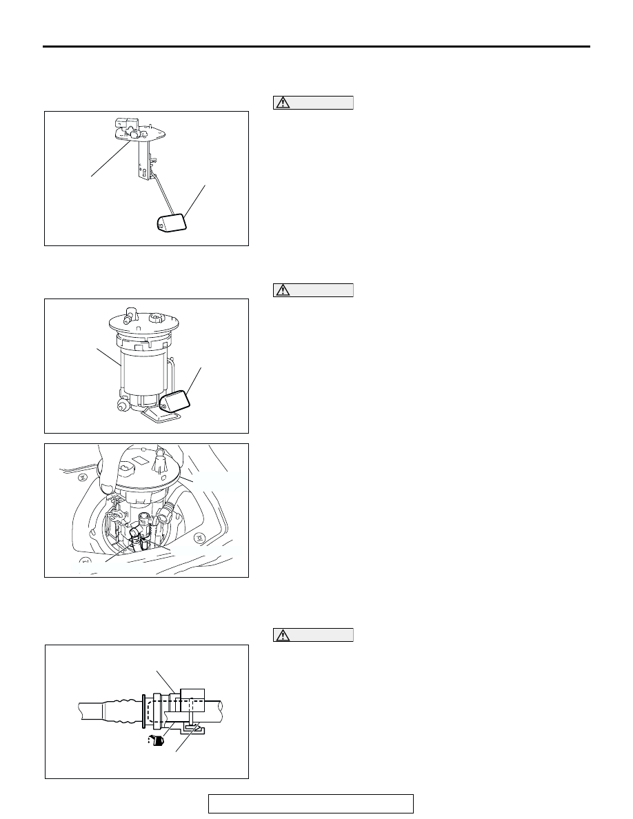
>>A<< FUEL LEVEL SENSOR (SUB) INSTALLATION

CAUTION

When inserting the fuel level sensor (sub) into the fuel 
tank, be careful not to damage the sensor unit and the 
float.

.

>>B<< FUEL PUMP MODULE INSTALLATION

CAUTION

When installing the fuel pump module into the fuel tank, be 
careful not to damage the module unit and the float.

1. Align the mark of the suction hose with that of the fuel pump 

module, and then connect the suction hose to the fuel pump 
module.

2. Install the fuel pump module into the fuel tank while ensuring 

that the suction hose is not kinked.

.

>>C<< FUEL HIGH-PRESSURE HOSE/FUEL 
HIGH-PRESSURE HOSE CONNECTION INSTALLATION

CAUTION

Connect the fuel high-pressure hose, and then pull it gen-
tly in the direction of removal to check that the hose is 
firmly connected.
Apply clean engine oil to the tips of the main pipe nozzle and 
the fuel main pipe, and connect connector of the fuel high-pres-
sure hose to them.

AC307206AB

FLOAT

FUEL LEVEL 
SENSOR (SUB)

AC307207

FUEL PUMP 
MODULE

FLOAT

AB

AC306092AB

SUCTION HOSE

FUEL PUMP 
MODULE

MATING MARKS

AC209221

CONNECTOR

MAIN PIPE NOZZLE OR
FUEL MAIN PIPE

AB

FUEL TANK

TSB Revision

FUEL SUPPLY

13C-16

.

>>D<< FUEL TANK ASSEMBLY/FUEL TANK BAND 
INSTALLATION
1. Raise the fuel tank assembly carefully with a transaxle jack.
2. Ensure that the fuel tank assembly does not interfere with 

surrounding parts. Then install the fuel tank band and 
tighten the mounting nuts to the specified torque.

Tightening torque: 26 

± 4 Nm (19 ± 3 ft-lb)

3. Again, ensure that the fuel tank assembly does not interfere 

with surrounding components. If the fuel tank assembly 
interferes surrounding components, remove the fuel tank 
assembly and the tank band and reinstall them.

INSPECTION

M1135002000241

.

Fuel Shut-off Valve Check
Check that the flapper of the fuel shut-off valve opens and 
closes as shown in the illustration.

.

Fuel Tank Differential Pressure Sensor Check

Requird Special Tool:

• MB991658: Test harness set

1. Disconnect the fuel tank differential pressure sensor 

connector and connect special tool MB991658 between the 
terminals of the disconnected connector.

2. Turn the ignition switch to “ON” position and measure the 

voltage between terminal 1 and ground.

Standard value: 2.0 

 3.0 V

AC005004AB

CLOSED

OPEN

FLAPPER

80˚

AC002081AB

MB991658

FUEL TANK DIFFERENTIAL 
PRESSURE SENSOR

SPECIFICATIONS

TSB Revision

FUEL SUPPLY

13C-17

SPECIFICATIONS

FASTENER TIGHTENING SPECIFICATIONS

M1135003900322

SERVICE SPECIFICATION

M1135000300257

ITEM

SPECIFICATIONS

Fuel tank band nut

26 

± 4 N⋅m (19 ± 3 ft-lb)

Hole cover screw

1.5 

± 0.5 N⋅m (14 ± 4 in-lb)

ITEM

STANDARD VALUE

Fuel tank differential pressure sensor output voltage V

2.0 

− 3.0

NOTES


Content   ..  1665  1666  1667  1668   ..