Mitsubishi Galant (2004+). Manual - part 1602


  Index      Mitsubishi     Mitsubishi Galant - service repair manual 2004 year


Search            


Content   ..  1600  1601  1602  1603   ..


Mitsubishi Galant (2004+). Manual - part 1602


SRS AIR BAG DIAGNOSIS

TSB Revision

SUPPLEMENTAL RESTRAINT SYSTEM (SRS)

52B-301

STEP 5. Recheck for diagnostic trouble code. 

Check again if the DTC is set.
(1) Erase the DTC.
(2) Turn the ignition switch to the "ON" position.
(3) Check if the DTC is set.
(4) Turn the ignition switch to the "LOCK" (OFF) position.
Q: Is DTC B1519 set?

YES : Return to Step 1 .
NO :  The procedure is complete. 
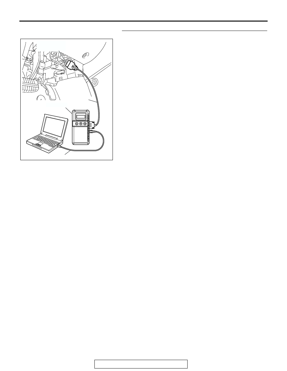
AC305412

AB

MB991910

DATA LINK

CONNECTOR

MB991824

MB991827

SRS AIR BAG DIAGNOSIS

TSB Revision

SUPPLEMENTAL RESTRAINT SYSTEM (SRS)

52B-302

DTC B1520: Seat belt switch (RH) malfunction DTC B1521: Seat belt switch (RH) circuit open (for 
Normal/Close terminal) DTC B1522: Seat belt switch (RH) circuit (ground side) shorted (for 
Normal/Close terminal) DTC B1523: Seat belt switch (RH) circuit (power supply side) shorted (for 
Normal/Close terminal) DTC B1524: Seat belt switch (RH) circuit open (for Normal/Open terminal) DTC 
B1525: Seat belt switch (RH) circuit (ground side) shorted (for Normal/Open terminal) DTC B1526: 
Seat belt switch (RH) circuit (power supply side) shorted (for Normal/Open terminal) DTC B1527: Seat 
belt switch (RH) circuit open (for COM terminal) DTC B1528: Seat belt switch (RH) circuit (ground 
side) shorted (for COM terminal) DTC B1529: Seat belt switch (RH) circuit (power supply side) shorted 
(for COM terminal)

CAUTION

If DTC B1520, B1521, B1522, B1523, B1524, 
B1525, B1526, B1527, B1528 or B1529 are set in 
the combination meter, always diagnose the CAN 
bus lines.

.

CIRCUIT OPERATION
The SRS-ECU determines whether the seat belt is 
fastened or not according to the connection location 
of the seat belt switch in the seat buckle.

.

SEAT BELT
SWITCH
(PASSENGER'S SIDE)

SRS-ECU

SEAT BELT
SWITCH (PASSENGER'S SIDE)
DETECTION CIRCUIT

Passenger's Seat Belt Switch Circuit

AC305362

CONNECTOR: C-120

C-120 (Y)

AC

SRS-ECU

AC305264

AR

CONNECTOR: D-29

SRS AIR BAG DIAGNOSIS

TSB Revision

SUPPLEMENTAL RESTRAINT SYSTEM (SRS)

52B-303

DTC SET CONDITIONS
DTC is set when the resistance between input termi-
nals of the seat belt switch in the SRS-ECU is with-
out the standard value.

Cause of trouble in each DTC is as follows.

.

TROUBLESHOOTING HINTS

• Malfunction of the seat belt switch

• Damaged wiring harnesses or connectors 

• Malfunction of the SRS-ECU 

DIAGNOSIS

Required Special Tools:

• MB991222: Probe

• MB991958: Scan Tool (MUT-III Sub Assembly)

• MB991824: Vehicle Communication Interface (V.C.I.)

• MB991827: MUT-III USB Cable

• MB991910: MUT-III Main Harness A (Vehicles with CAN 

communication system)

DTC

SYMPTOM

B1520

Malfunction of seat belt switch 

B1521

Malfunction of the Normal/Close terminal or short circuit in its harness

B1522

Short to body ground in the Normal/Close terminal harness

B1523

Short to the power supply in the Normal/Close terminal harness

B1524

Malfunction of the Normal/Open terminal or short circuit in its harness

B1525

Short to body ground in the Normal/Open terminal harness

B1526

Short to the power supply in the Normal/Open terminal harness

B1527

Malfunction of the COM terminal or short circuit in its harness

B1528

Short to body ground in the COM terminal harness

B1529

Short to the power supply in the COM terminal harness

SRS AIR BAG DIAGNOSIS

TSB Revision

SUPPLEMENTAL RESTRAINT SYSTEM (SRS)

52B-304

STEP 1. Using scan tool MB991958, diagnose the CAN bus 
line.

CAUTION

To prevent damage to scan tool MB991958, always turn the 
ignition switch to the "LOCK" (OFF) position before con-
necting or disconnecting scan tool MB991958.
(1) Connect scan tool MB991958. Refer to "How to connect the 

scan tool 

P.52B-30

."

(2) Connect scan tool MB991958 to the data link connector.
(3) Turn the ignition switch to the "ON" position.
(4) Diagnose the CAN bus line.
(5) Turn the ignition switch to the "LOCK" (OFF) position.
Q: Is the CAN bus line found to be normal?

YES : Go to Step 3.
NO :  Repair the CAN bus line (Refer to GROUP 54C, 

Diagnosis 

P.54C-14

). Then go to Step 2.

STEP 2. Recheck for diagnostic trouble code.

Check again if the DTC is set.
(1) Erase the DTC.
(2) Turn the ignition switch to "ON" position.

(3) Check if the DTC is set.
(4) Turn the ignition switch to the "LOCK" (OFF) position.
Q: Is the DTC set?

YES : Go to Step 3. 
NO :  There is an intermittent malfunction such as poor 

engaged connector(s) or open circuit (Refer to 
GROUP 00, How to Cope with Intermittent 
Malfunction 

P.00-6

).

AC305412

AB

MB991910

DATA LINK

CONNECTOR

MB991824

MB991827

AC305412

AB

MB991910

DATA LINK

CONNECTOR

MB991824

MB991827


Content   ..  1600  1601  1602  1603   ..