Content .. 1599 1600 1601 1602 ..
Mitsubishi Galant (2004+). Manual - part 1601
SRS AIR BAG DIAGNOSIS
TSB Revision
SUPPLEMENTAL RESTRAINT SYSTEM (SRS)
52B-297
STEP 2. Recheck for diagnostic trouble code.
Check again if the DTC is set.
(1) Erase the DTC.
(2) Turn the ignition switch to the "ON" position.
(3) Check if the DTC is set.
(4) Turn the ignition switch to the "LOCK" (OFF) position.
Q: Is the DTC B1499 set?
YES : Replace the SRS-ECU (Refer to
).
NO : There is an intermittent malfunction such as poor
engaged connector(s) or open circuit (Refer to
GROUP 00, How to Cope with Intermittent
Malfunction
DTC B1519: Connector Lock System Detects Connector Unlocked
CAUTION
If DTC B1519 is set in the SRS-ECU, always diag-
nose the CAN main bus line.
.
DTC SET CONDITIONS
This DTC is set if a poor connection at the SRS-ECU
is detected. However, if the vehicle condition returns
to normal, DTC number B1519 will be automatically
erased, and the SRS warning light will go out.
.
TROUBLESHOOTING HINTS
• Damaged connectors
• Malfunction of the SRS-ECU
.
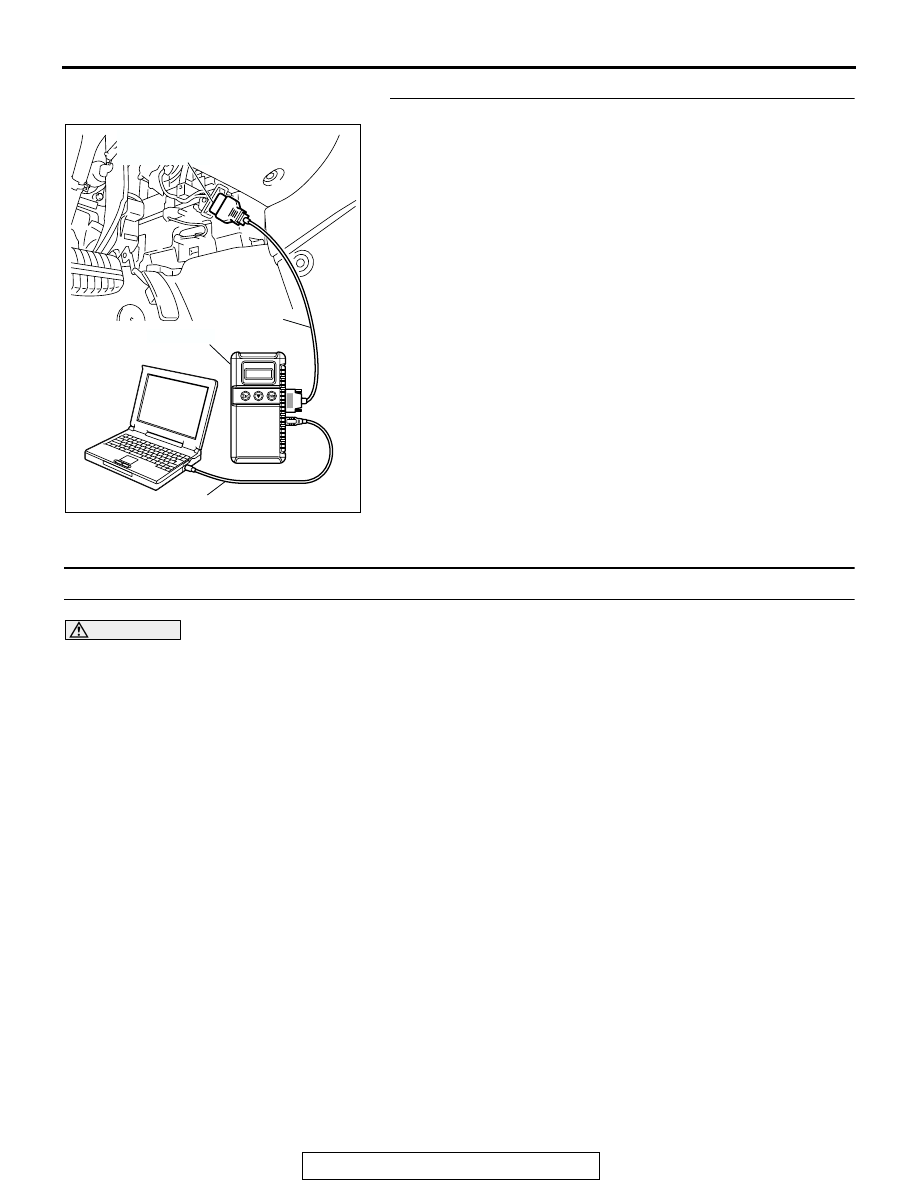
DIAGNOSIS
Required Special Tool:
• MB991958: Scan Tool (MUT-III Sub Assembly)
• MB991824: Vehicle Communication Interface (V.C.I.)
• MB991827: MUT-III USB Cable
• MB991910: MUT-III Main Harness A (Vehicles with CAN
communication system)
AC305412
AB
MB991910
DATA LINK
CONNECTOR
MB991824
MB991827