Mitsubishi Galant (2004+). Manual - part 1544


  Index      Mitsubishi     Mitsubishi Galant - service repair manual 2004 year


Search            


Content   ..  1542  1543  1544  1545   ..


Mitsubishi Galant (2004+). Manual - part 1544


SRS AIR BAG DIAGNOSIS

TSB Revision

SUPPLEMENTAL RESTRAINT SYSTEM (SRS)

52B-69

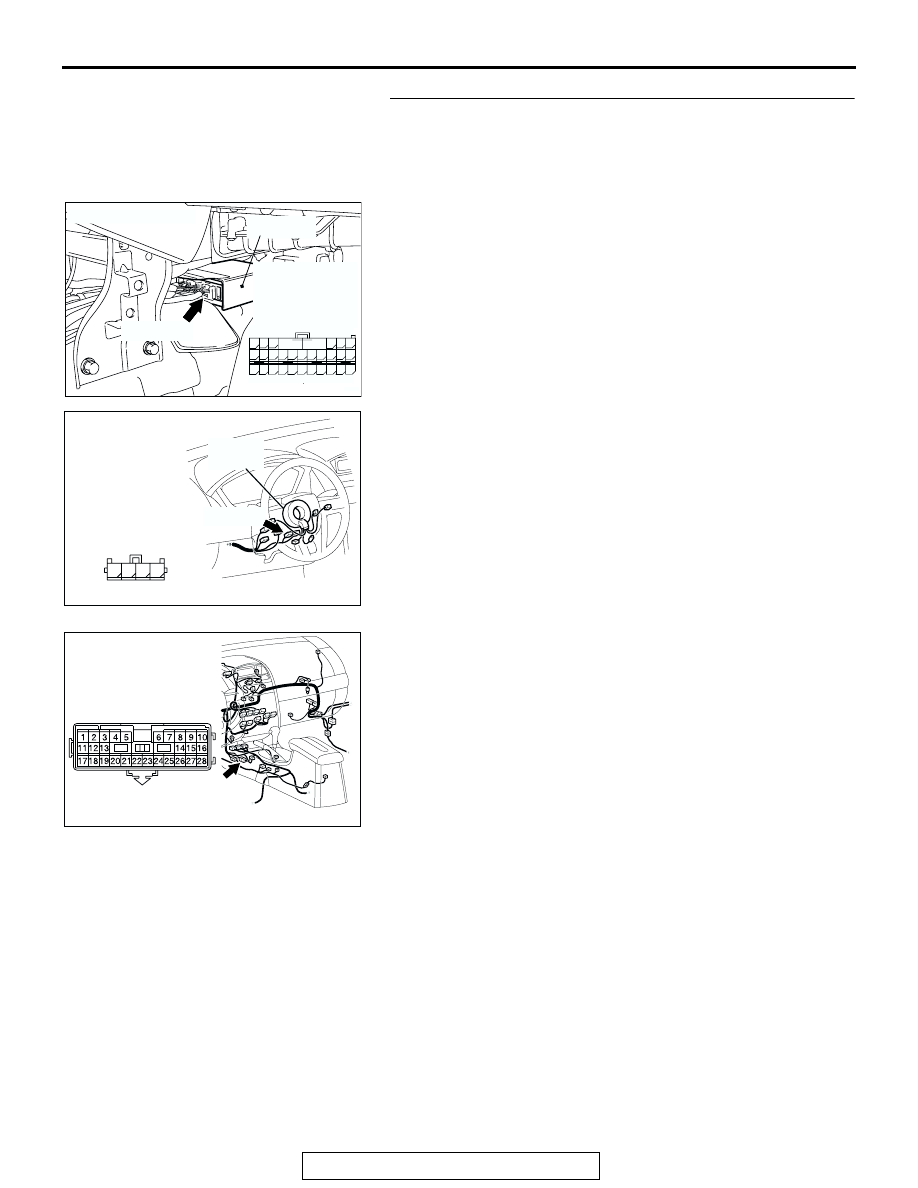
STEP 6. Check the harness for short circuit to ground 
between SRS-ECU connector C-121 (terminal No.36 and 37 
<1st squib> or terminal No.33 and 34 <2nd squib>) and 
clock spring connector C-307 (terminal No.13 and 14 or 
terminal No. 11 and 12 <2nd squib>).

NOTE: After inspecting intermediate connector C-22 inspect 
the wiring harness. If the intermediate connector C-22 is dam-
aged, repair or replace it.
Q: Are the harness wires between SRS-ECU connector 

C-121 (terminal No.36 and 37 <1st squib> or terminal 
No.33 and 34 <2nd squib>) and clock spring connector 
C-307 (terminal No.13 and 14 or terminal No. 11 and 12 
<2nd squib>) in good condition?
YES : 
Go to Step 7.
NO :  Replace the harness wires between SRS-ECU 

connector C-121 and clock spring connector C-307. 
Then go to Step 7.

AC305362

CONNECTOR: C-121

C-121 (Y)

AH

SRS-ECU

C-121
HARNESS SIDE 
CONNECTOR
(REAR VIEW)

42

31

38

27

21

41

28

39

22

30

25

47

36

33

44

34

45

37

48

26

29

23

40

32

43

35

46

24

B

A

AC305235AK

C-307 (Y)

CONNECTOR: C-307

C-307 HARNESS
SIDE CONNECTOR

CLOCK
SPRING

11

12

13

14

AC305233

C-22 (Y)

CO

CONNECTOR: C-22

SRS AIR BAG DIAGNOSIS

TSB Revision

SUPPLEMENTAL RESTRAINT SYSTEM (SRS)

52B-70

STEP 7. Recheck for diagnostic trouble code. 

Check again if the DTC is set.
(1) Erase the DTC.
(2) Turn the ignition switch to the "ON" position.
(3) Check if the DTC is set.
(4) Turn the ignition switch to the "LOCK" (OFF) position.
Q: Is DTC B1403 <1st squib> or B1483 <2nd squib> set?

YES : Return to Step 1.
NO :  The procedure is complete.

DTC B1406: Front Impact Sensor (RH) System for Fault 1 DTC B1416: Front Impact Sensor (LH) 
System for Fault 1

CAUTION

If DTC B1406 or B1416 is set in the SRS-ECU, 
always diagnose the CAN main bus line.

.

DTC SET CONDITIONS
These DTCs are set if the following conditions are 
detected from the analog G-sensor inside the side 
impact sensor output:

• Analog G-sensor is not operating.

• Analog G-sensor characteristics are abnormal.

• Analog G-sensor output is abnormal.

.

TROUBLESHOOTING HINTS
Malfunction of front impact sensor (RH) (for DTC 
B1406) and front impact sensor (LH) (for DTC 
B1416)

.

DIAGNOSIS

Required Special Tool:

• MB991958: Scan Tool (MUT-III Sub Assembly)

• MB991824: Vehicle Communication Interface (V.C.I.)

• MB991827: MUT-III USB Cable

• MB991910: MUT-III Main Harness A (Vehicles with CAN 

communication system)

AC305412

AB

MB991910

DATA LINK

CONNECTOR

MB991824

MB991827

SRS AIR BAG DIAGNOSIS

TSB Revision

SUPPLEMENTAL RESTRAINT SYSTEM (SRS)

52B-71

STEP 1. Using scan tool MB991958, diagnose the CAN bus 
line.

CAUTION

To prevent damage to scan tool MB991958, always turn the 
ignition switch to the "LOCK" (OFF) position before con-
necting or disconnecting scan tool MB991958.
(1) Connect scan tool MB991958. Refer to "How to connect the 

scan tool 

P.52B-30

."

(2) Turn the ignition switch to the "ON" position.
(3) Diagnose the CAN bus line.
(4) Turn the ignition switch to the "LOCK" (OFF) position.
Q: Is the CAN bus line found to be normal?

YES : Go to Step 2.
NO :  Repair the CAN bus line (Refer to GROUP 54C, 

Diagnosis 

P.54C-14

).

STEP 2. Recheck for diagnostic trouble code.

Check again if the DTC is set.
(1) Erase the DTC.
(2) Turn the ignition switch to the "ON" position.

(3) Check if the DTC is set.
(4) Turn the ignition switch to the "LOCK" (OFF) position.
Q: Is the DTC set?

YES : Go to Step 3.
NO :  There is an intermittent malfunction such as poor 

engaged connector(s) or open circuit (Refer to 
GROUP 00, How to Cope with Intermittent 
Malfunction 

P.00-6

).

AC305412

AB

MB991910

DATA LINK

CONNECTOR

MB991824

MB991827

AC305412

AB

MB991910

DATA LINK

CONNECTOR

MB991824

MB991827

SRS AIR BAG DIAGNOSIS

TSB Revision

SUPPLEMENTAL RESTRAINT SYSTEM (SRS)

52B-72

STEP 3. Check the front impact sensor. (Using scan tool 
MB991958, read the diagnostic trouble code.)

Replace front impact sensor (RH) and front impact sensor (LH) 
(for DTC B1416) (Refer to 

P.52B-362

).

Check the diagnostic trouble code.
Q: Is either DTC B1406 or B1416 set?

YES : Replace the SRS-ECU (Refer to 

P.52B-365

).

NO :  The procedure is complete.

DTC B1407: Front Impact Sensor (RH) Power Supply Circuit System

INTERFACE CIRCUIT

SRS-ECU

FRONT IMPACT 
SENSOR (LH)

FRONT IMPACT 
SENSOR (RH)

Front Impact Sensor Circuit

AC305206

A-27 (Y)

BC

CONNECTOR: A-27

AC305233CV

CONNECTOR: C-11


Content   ..  1542  1543  1544  1545   ..