Content .. 1534 1535 1536 1537 ..
Mitsubishi Galant (2004+). Manual - part 1536
SRS AIR BAG DIAGNOSIS
TSB Revision
SUPPLEMENTAL RESTRAINT SYSTEM (SRS)
52B-37
NOTE:
*1
: Electrically Erasable Programmable ROM
*2
: This DTC will remain in memory and the SRS warning light will be switched off when the system returns to
normal condition.
*3
: This DTC will remain in memory and the SRS warning light will be switched on even if the system returns
to normal condition.
*4
: This DTC will remain in memory when the front passenger's air bag is inactive condition in the event of an
impact.
*5
: This DTC cannot be erased by "Erase DTCs" function.
B1538
*3
Seat belt switch (LH) circuit (ground side) shorted (for COM
termnal)
B1539
*3
Seat belt switch (LH) circuit (power supply side) shorted (for
COM termnal)
B1540
*3
Occupant classification-ECU malfunction
B1541
*3
Occupant classification-ECU calibration malfunction
B1542
*3
Occupant classification sensor (S1) malfunction
B1543
*3
Occupant classification sensor (S2) malfunction
B1545
*3
Occupant classification-ECU communication error
B1546
*3
Occupant classification-ECU communication impossible
B1547
*4*5
Cut OFF for passenger’s front air bag
B1552
*5
Changing circuit shorted
B1553
*5
Changing circuit open
B1554
*5
SG BY-PASS circuit malfunction
B1555
*5
SG BY-PASS circuit (FET) open
B1556
*3
Seat slide sensor malfunction
B1557
*5
SRS-ECU ASIC
B1558
*3
Occupant classification-ECU ID-cord malfunction
U1073
*2
Bus-off
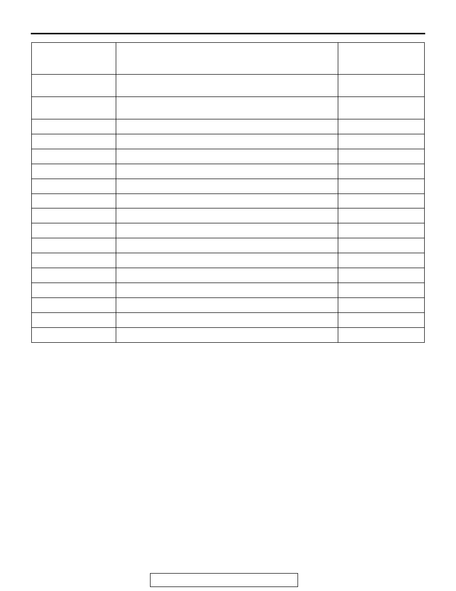
DIAGNOSTIC
TROUBLE CODE
NO.
INSPECTION ITEM
REFERENCE PAGE