Mitsubishi Galant (2004+). Manual - part 1534


  Index      Mitsubishi     Mitsubishi Galant - service repair manual 2004 year


Search            


Content   ..  1532  1533  1534  1535   ..


Mitsubishi Galant (2004+). Manual - part 1534


SERVICE PRECAUTIONS

TSB Revision

SUPPLEMENTAL RESTRAINT SYSTEM (SRS)

52B-29

WARNING

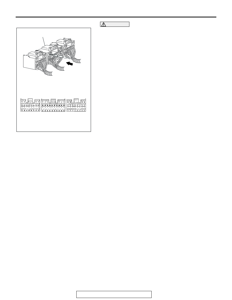
Inspection of the SRS-ECU connector harness 
should be carried out by the following procedure. 
Insert the backprobing tool into connector from 
harness side (rear side), and connect the tester to 
backprobing tool. If any tool other than backprob-
ing tool is used, it may cause damage to the har-
ness and other components. Furthermore, 
measurement should not be carried out by touch-
ing the backprobing tool directly against the termi-
nals from the front of the connector. The terminals 
are plated to increase their conductivity, so if they 
are touched directly by the backprobing tool, the 
plating may break, which will decrease reliability.

The SRS components and seat belt with 
pre-tensioner should not be subjected to heat, so 
remove the SRS-ECU, driver’s and front passen-
ger’s air bag modules, clock spring, side-airbag 
modules, and seat belt pre-tensioner before drying 
or baking the vehicle after painting.

SRS-ECU, air bag module, clock spring: 93

°

 C 

(200

°

 F) or more

Seat belt with pre-tensioner 90

°

C (194

°

 F) or 

more

After servicing the SRS system, check the warning 
light operation to make sure that the system func-
tions properly. (Refer to 

P.52B-3

).

Make certain that the ignition switch is in the 
"LOCK"(OFF) position when the scan tool is con-
nected or disconnected.

AC307379

AC301599

AC300928

SRS-HARNESS CONNECTOR

SRS-ECU HARNESS CONNECTOR
(REAR SIDE)

AB

SRS AIR BAG DIAGNOSIS

TSB Revision

SUPPLEMENTAL RESTRAINT SYSTEM (SRS)

52B-30

SRS AIR BAG DIAGNOSIS

INTRODUCTION TO DIAGNOSIS

M1524005000330

The SRS system is controlled by the SRS-ECU. The 
SRS-ECU judges how severe a collision is by detect-
ing signals from the left and right front impact sen-
sors and side impact sensors, front air bag analog 
G-sensor and front air bag safing G-sensor and 
side-airbag safing G-sensor. If the impact is over a 
predetermined level, the SRS-ECU sends an ignition 
signal. At this time, if the safing G-sensor is on, the 
SRS air bag will inflate. (The passenger's air bag 
may not inflate according to the occupant detection 
data from the occupant classification-ECU.) The 

SRS warning light in the combination meter alerts a 
malfunction of the SRS system. If the following 
symptoms occur even when the vehicle has not been 
in a collision, there may be a malfunction in the SRS 
system.

• The SRS warning light does not go off within 

approximately seven seconds after the ignition 
switch has been turned to the "ON" position.

• The SRS warning light does not illuminate when 

the ignition switch is turned to the "ON" position.

Refer to Post-collision Diagnosis when inspecting 
and servicing a vehicle that has been in a collision 
(Refer to 

P.52B-348

).

TROUBLESHOOTING STRATEGY

M1524003100427

Use these steps to plan your diagnostic strategy. If 
you follow them carefully, you will be sure that you 
have exhausted all of the possible ways to find a 
SRS fault.
1. Gather information about the problem from the 

customer.

2. Verify that the condition described by the 

customer exists.

3. Check the vehicle for any SRS diagnostic trouble 

codes (SRS DTC).

4. If you cannot verify the condition but there are no 

SRS DTCs, the malfunction is intermittent. Refer 
to GROUP 00, How to Use Troubleshooting 

− 

Inspection Service Points 

− How to Cope with 

Intermittent Malfunctions 

P.00-6

.

5. If there is a SRS DTC, record the code number, 

then erase the code from vehicle memory using 
scan tool (MUT-III Sub Assembly) MB991958.

6. Recreate the SRS DTC set conditions to see if the 

same SRS DTC will be set again.

• If the same SRS DTC is set again, follow the 

Inspection Chart for the DTC and find the fault.

• If you cannot get the same SRS DTC to be set 

again, the malfunction is intermittent. Refer to 
GROUP 00, How to Use Troubleshooting 

− 

Inspection Service Points 

− How to Cope with 

Intermittent Malfunctions 

P.00-6

.

DIAGNOSTIC FUNCTION

M1524013800074

HOW TO CONNECT THE SCAN TOOL (MUT-III)

Required Special Tools:

•  MB991958: Scan Tool (MUT-III Sub Assembly)

• MB991824: Vehicle Communication Interface (V.C.I.)

• MB991827: MUT-III USB Cable

• MB991910: MUT-III Main Harness A (Vehicles with CAN 

communication system)

SRS AIR BAG DIAGNOSIS

TSB Revision

SUPPLEMENTAL RESTRAINT SYSTEM (SRS)

52B-31

CAUTION

To prevent damage to scan tool MB991958, always turn the 
ignition switch to the "LOCK" (OFF) position before con-
necting or disconnecting scan tool MB991958.
1. Ensure that the ignition switch is at the "LOCK" (OFF) 

position.

2. Start up the personal computer.
3. Connect special tool MB991827 to special tool MB991824 

and the personal computer.

4. Connect special tool MB991910 to special tool MB991824.
5. Connect special tool MB991910 to the data link connector.
6. Turn the power switch of special tool MB991824 to the "ON" 

position.
NOTE: When special tool MB991824 is energized, special 
tool MB991824 indicator light will be illuminated in a green 
color.

7. Start the MUT-III system on the personal computer.
NOTE: Disconnecting scan tool MB991958 is the reverse of the 
connecting sequence, making sure that the ignition switch is at 
the "LOCK" (OFF) position.

HOW TO READ AND ERASE DIAGNOSTIC 
TROUBLE CODES

Required Special Tools:

•  MB991958: Scan Tool (MUT-III Sub Assembly)

• MB991824: Vehicle Communication Interface (V.C.I.)

• MB991827: MUT-III USB Cable

• MB991910: MUT-III Main Harness A (Vehicles with CAN 

communication system)

CAUTION

To prevent damage to scan tool MB991958, always turn the 
ignition switch to the "LOCK" (OFF) position before con-
necting or disconnecting scan tool MB991958.
NOTE: If the battery voltage is low, diagnostic trouble codes will 
not be set. Check the battery if scan tool MB991958 does not 
display.
1. Connect scan tool MB991958 to the data link connector.
2. Turn the ignition switch to the "ON" position.
3. Select "Interactive Diagnosis" from the start-up screen.
4. Select "System select."
5. Select "MITSUBISHI."
6. Choose "SRS-AIR BAG" from the "BODY" tab.
7. Select "Diagnostic Trouble Code."
8. If a DTC is set, it is shown.
9. Choose "Erase DTCs" to erase the DTC.

AC305412

AB

MB991910

DATA LINK

CONNECTOR

MB991824

MB991827

AC305412

AB

MB991910

DATA LINK

CONNECTOR

MB991824

MB991827

SRS AIR BAG DIAGNOSIS

TSB Revision

SUPPLEMENTAL RESTRAINT SYSTEM (SRS)

52B-32

SRS WARNING LIGHT CHECK

M1524004300361

1. Check that the SRS warning light illuminates when the 

ignition switch is in the "ON" position.

2. Check that it illuminates for approximately seven seconds 

and then goes out.

3. If not, check for DTC.

PASSENGER'S SEAT BELT WARNING LIGHT 
CHECK

M1524026200016

1. Check that the passenger’s seat belt warning light 

illuminates when the ignition switch is in the "ON" position.

2. Check that it illuminates for approximately seven seconds 

and then goes out.

3. If not, check for DTC.

PASSENGER'S AIR BAG OFF INDICATOR LIGHT 
CHECK

M1524026300013

1. Check that the passenger’s air bag OFF indicator light 

illuminates when the ignition switch is in the "ON" position.

2. Check that it illuminates for approximately seven seconds 

and then goes out.

3. If not, check for DTC.

AC307341

SRS WARNING LIGHT

AB

AC306329AC

PASSENGER'S 
SEAT BELT
WARNING 
LIGHT

AC306329AB

PASSENGER'S 
AIR BAG OFF
INDICATOR 
LIGHT


Content   ..  1532  1533  1534  1535   ..