Mitsubishi Galant (2004+). Manual - part 1526


  Index      Mitsubishi     Mitsubishi Galant - service repair manual 2004 year


Search            


Content   ..  1524  1525  1526  1527   ..


Mitsubishi Galant (2004+). Manual - part 1526


ON-VEHICLE SERVICE

TSB Revision

TRACTION CONTROL SYSTEM (TCL)

13D-45

ON-VEHICLE SERVICE

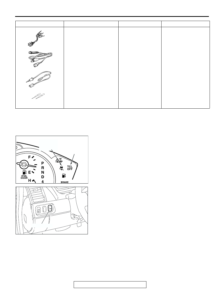
TCL INDICATOR LIGHT CHECK

M1136000900025

1. Check that the "TCL OFF" indicator light and the TCL work 

indicator light illuminate for three seconds when the ignition 
switch is turned to the "ON" position.

2. Check that the "TCL OFF" indicator light illuminates and 

goes off in cycles each time the TCL switch is pushed after 
starting the engine.

3. Check that the "TCL OFF" indicator light and the TCL work 

indicator light do not illuminate, when driving at 30km/h 
(37.5 mph) for more than 2 seconds.

4. If defective, repair it. (Refer to the TCL diagnosis section.) 

(Refer to 

P.13D-3

).

MB991223

A: MB991219
B: MB991220
C: MB991221
D: MB991222

Harness set

A: Inspection harness
B: LED harness
C: LED harness adapter
D: Probe

General service tools

Checking the continuity 
and measuring the 
voltage at the harness 
connector

TOOL

TOOL NUMBER AND NAME SUPERSESSION

APPLICATION

MB991223

A

D

C

B

AD

AC305706

"TCL OFF"
INDICATOR
LIGHT

TCL WORK
INDICATOR
LIGHT

AB

AC305707

TCL SWITCH

AB

ON-VEHICLE SERVICE

TSB Revision

TRACTION CONTROL SYSTEM (TCL)

13D-46

TCL OPERATION CHECK

M1136001100022

Required Special Tool:

• MB991958: Scan tool (MUT-III sub assembly)

• MB991824: V.C.I.

• MB991827: MUT-III USB cable

• MB991910: MUT-III main harness A

CAUTION

To prevent damage to scan tool MB991958, always turn the 
ignition switch to the "LOCK" (OFF) position before con-
necting or disconnecting scan tool MB991958.
1. Connect scan tool MB991958 to the data link connector 

(Refer to 

P.13D-4

).

2. Turn the ignition switch to the "ON" position.

CAUTION

The engine speed increases after the actuator test 
because the actuator test continues for only three sec-
onds. Therefore, release the accelerator pedal immedi-
ately. 
3. Use scan tool MB991958 to check the actuator test item 09: 

Engine TCL Drive.

• When the accelerator pedal is depressed at the same time 

that the button for actuator test item 09 displayed on scan 
tool MB991958 is pressed, the system prevents the engine 
speed from rising for three seconds.

4. Turn the ignition switch to the "LOCK" (OFF) position.
5. Disconnect scan tool MB991958.
6. If defective, repair it. (Refer to TCL diagnosis - Symptom 

Procedure.) (Refer to 

P.13D-39

).

TCL SWITCH CHECK

M1136001700024

1. Remove the TCL switch. (Refer to 

P.13D-47

).

2. Measure the resistance between terminal 1 and terminal 2 

when the TCL switch is pressed or released. If the values 
measured at the time correspond to those in the table below, 
the resistance values are correct.

WHEEL SPEED SENSOR CHECK

M1136001300026

Refer to GROUP 35B - On-vehicle Service 

P.35B-104

.

AC305412

AB

MB991910

DATA LINK

CONNECTOR

MB991824

MB991827

SWITCH 
POSITION

TESTER 
CONNECTION

SPECIFIED 
CONDITION

Pressed

1-2

Less than 2 
ohms

Released

1-2

Open circuit

AC307194AB

TCL SWITCH

TSB Revision

TRACTION CONTROL SYSTEM (TCL)

13D-47

TCL SWITCH

REMOVAL AND INSTALLATION

M1136001600027

WHEEL SPEED SENSOR

REMOVAL AND INSTALLATION

M1136002500023

Refer to GROUP 35B - Wheel Speed Sensor 

P.35B-112

.

ABS/TCL-ECU

REMOVAL AND INSTALLATION

M1136005300017

Replace the hydraulic unit (integrated with ABS/TCL-ECU) (Refer t0 GROUP 35B - Hydraulic Unit 

P.35B-109

).

AC307189

3

2

1

AB

REMOVAL STEPS

HOOD LOCK RELEASE HANDLE 
(REFER TO GROUP 42, HOOD 

P.42-8

.)

INSTRUMENT LOWER PANEL (REFER 
TO GROUP 52A, INSTRUMENT PANEL 
ASSEMBLY 

P.52A-3

.)

INSTRUMENT PANEL GARNISH 
(REFER TO GROUP 52A, 
INSTRUMENT PANEL ASSEMBLY 

P.52A-3

.)

1. SWITCH BEZEL ASSEMBLY
2. SWITCH PANEL ASSEMBLY
3. TCL SWITCH 

REMOVAL STEPS (Continued)

NOTES


Content   ..  1524  1525  1526  1527   ..