Content .. 1501 1502 1503 1504 ..
Mitsubishi Galant (2004+). Manual - part 1503
MULTI-CENTER DISPLAY
TSB Revision
CHASSIS ELECTRICAL
54A-255
Past trouble
• Carry out diagnosis with particular emphasis on
connector(s) or wiring harness in the CAN bus
lines between the ETACS-ECU and the
multi-center display unit (middle grade type), and
the power supply system to the ETACS-ECU. For
diagnosis procedures, refer to "How to cope with
past trouble" (Refer to GROUP 00, How to Use
Troubleshooting/Inspection Service Points
NOTE: For a past trouble, you may not find it by
the MUT-III CAN bus diagnostics even if there is
any failure in CAN bus lines. In this case, refer to
GROUP 00, How to Use Troubleshooting/Inspec-
tion Service Points-How to Cope with Intermittent
Malfunction
.) and check the CAN bus
lines. You can narrow down the possible cause of
the trouble by referring to the DTC, which is set
regarding the CAN communication-linked ECUs
(Refer to GROUP 54C, CAN bus line Diagnostics
Flow
.
TROUBLESHOOTING HINTS
• The wiring harness or connectors may have
loose, corroded, or damaged terminals, or termi-
nals pushed back in the connector.
• Malfunction of ETACS-ECU
• Malfunction of multi-center display unit (middle
grade type)
DIAGNOSIS
Required Special Tools:
• MB991958: Scan Tool (MUT-III Sub Assembly)
• MB991824: Vehicle Communication Interface (V.C.I.)
• MB991827: MUT-III USB Cable
• MB991911: MUT-III Main Harness A (Vehicles with CAN
communication system)
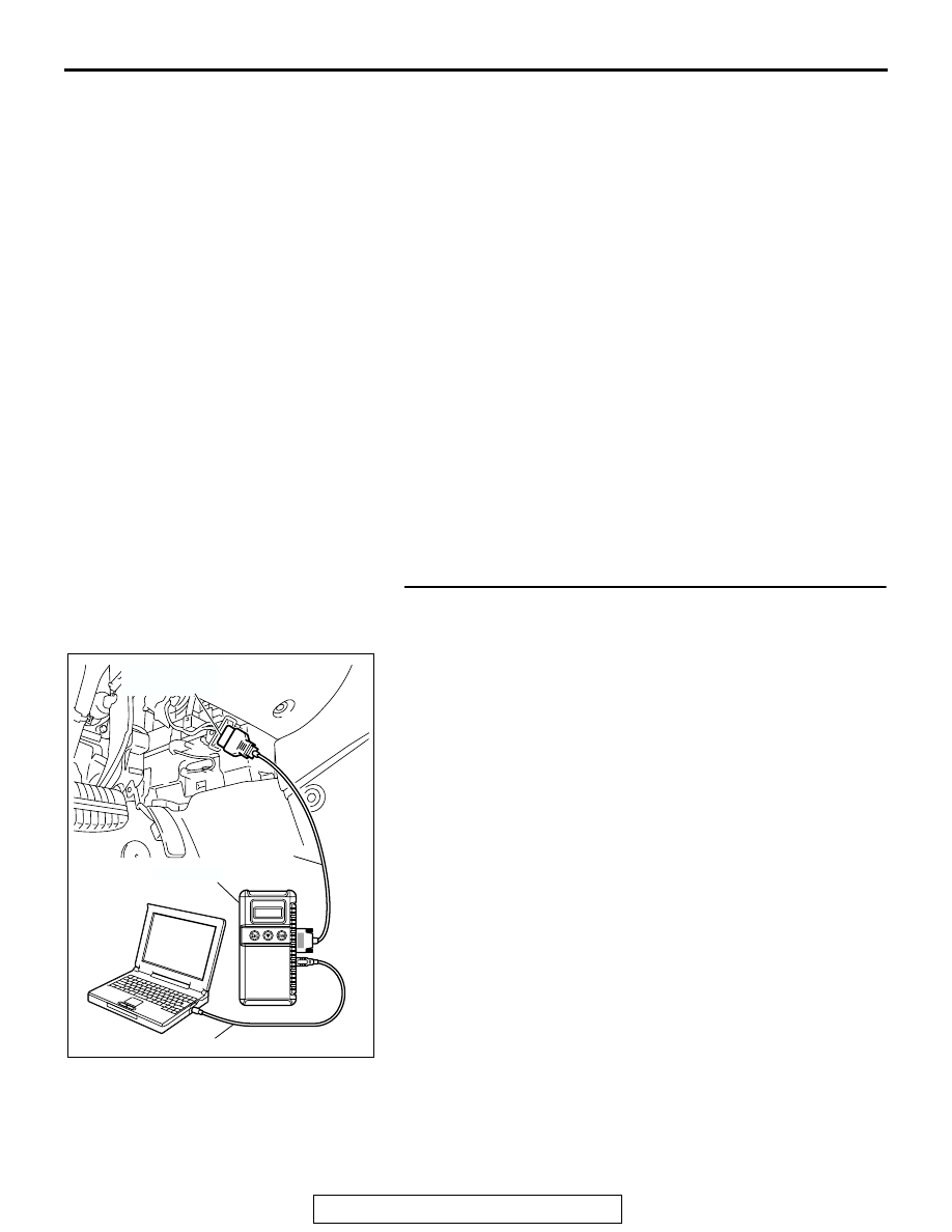
STEP 1. Using scan tool MB991958, diagnose the CAN bus
line.
Use scan tool MB991958 to diagnose the CAN bus lines.
(1) Connect scan tool MB991958 to the data link connector.
(2) Turn the ignition switch to "ON" position.
(3) Diagnose the CAN bus line.
Q: Is the check result satisfactory?
YES : Go to Step 2.
NO : Repair the CAN bus lines. (Refer to GROUP 54C,
Diagnosis-Can Bus Diagnostic Chart
completion, go to Step 6.
AC305412
AB
MB991910
DATA LINK
CONNECTOR
MB991824
MB991827