Mitsubishi Galant (2004+). Manual - part 1475


  Index      Mitsubishi     Mitsubishi Galant - service repair manual 2004 year


Search            


Content   ..  1473  1474  1475  1476   ..


Mitsubishi Galant (2004+). Manual - part 1475


RADIO WITH CD PLAYER

TSB Revision

CHASSIS ELECTRICAL

54A-143

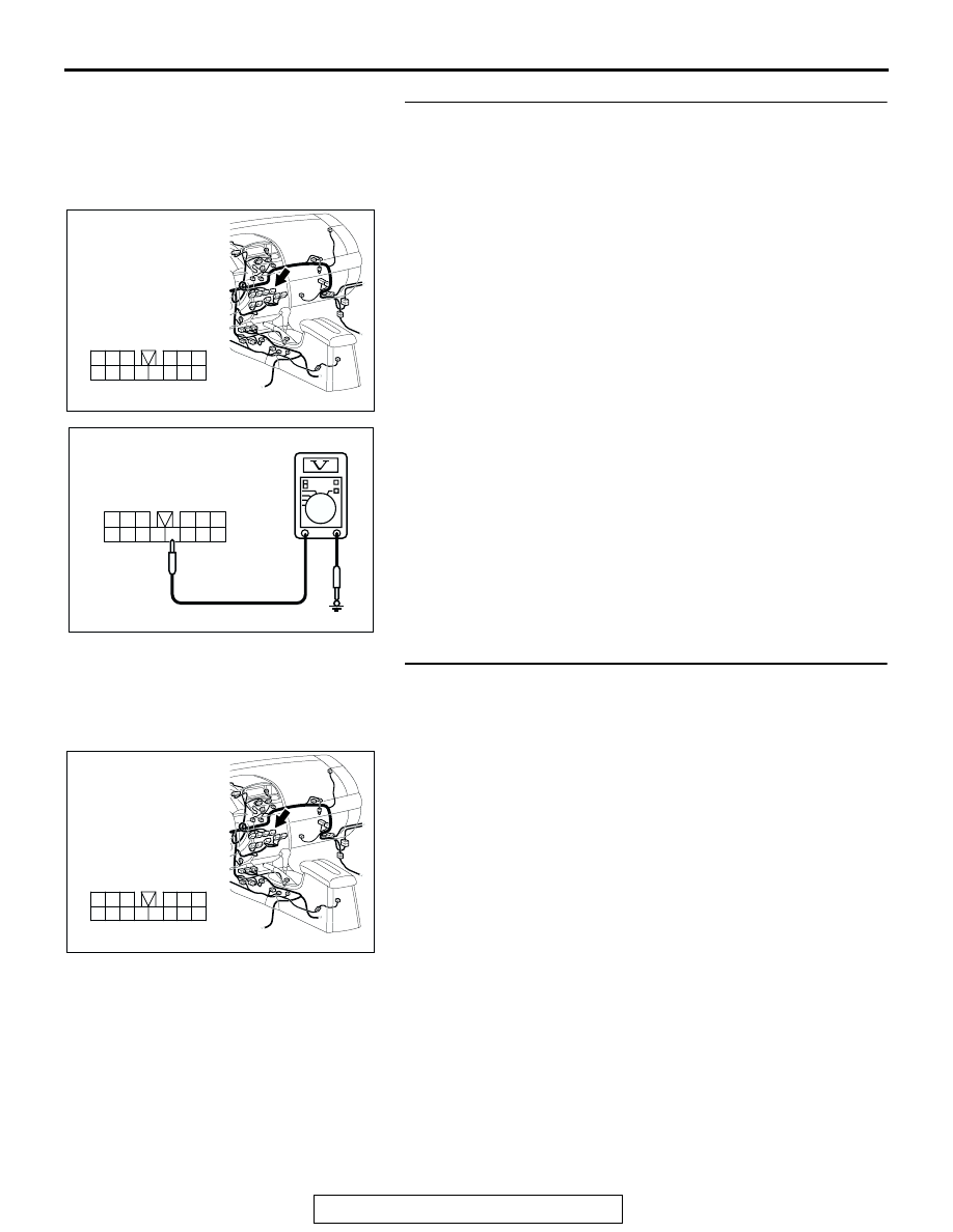
STEP 5. Measure at radio and CD player or radio, CD 
player and CD changer connector C-111 in order to check 
the battery circuit of power supply system to the radio and 
CD player or radio, CD player and CD changer (ignition 
switch ACC).
(1) Disconnect radio and CD player or radio, CD player and CD 

changer connector C-111, and measure at the wiring 
harness side.

(2) Turn the ignition switch to "ACC" position.

(3) Measure the voltage between terminal 10 and ground.

• The voltage should measure approximately 12 volts 

(battery positive voltage).

Q: Is the measured voltage approximately 12 volts (battery 

positive voltage)?
YES : 
Go to Step 8.
NO :  Go to Step 6.

STEP 6. Check radio and CD player or radio, CD player and 
CD changer connector C-111 for loose, corroded or 
damaged terminals, or terminals pushed back in the 
connector.
Q: Are radio and CD player or radio, CD player and CD 

changer connector C-111 in good condition?
YES : 
Go to Step 7.
NO :  Repair or replace the damaged component(s). Refer 

to GROUP 00E, Harness Connector Inspection 

P.00E-2

. If the power switch is turned on, the radio 

and CD player or radio, CD player and CD changer 
should operate normally.

AC305233

HARNESS SIDE

3
9

4

12

14

6

13

5

1110

8

2

7

1

BY

CONNECTOR: C-111

AC209365

3
9

4

12

14

6

13

5

1110

8

2

7

1

CONNECTOR C-111 
(HARNESS SIDE)

HV

AC305233

HARNESS SIDE

3
9

4

12

14

6

13

5

1110

8

2

7

1

BY

CONNECTOR: C-111

RADIO WITH CD PLAYER

TSB Revision

CHASSIS ELECTRICAL

54A-144

STEP 7. Check the wiring harness between radio and CD 
player or radio, CD player and CD changer connector 
C-111 (terminal 10) and ignition switch (ACC).

NOTE: Also check intermediate connector C-29 for loose, cor-
roded, or damaged terminals, or terminals pushed back in the 
connector. If intermediate connector C-29 is damaged, repair or 
replace the connector as described in GROUP 00E, Harness 
Connector Inspection 

P.00E-2

Q: Is the wiring harness between radio and CD player or 

radio, CD player and CD changer connector C-111 
(terminal 10) and ignition switch (ACC) in good 
condition?
YES : 
There is no action to be taken.
NO :  Repair the wiring harness. If the power switch is 

turned on, the radio and CD player or radio, CD player 
and CD changer should operate normally.

STEP 8. Check the installation condition of the radio and 
CD player or radio, CD player and CD changer.
NOTE: The radio and CD player or radio, CD player and CD 
changer are grounded to the deck crossmember directly.
Q: Are the radio and CD player or radio, CD player and CD 

changer installed correctly?
YES : 
Replace the radio and CD player or radio, CD player 

and CD changer. If the power switch is turned on, the 
radio and CD player or radio, CD player and CD 
changer should operate normally.

NO :  Install the radio and CD player or radio, CD player 

and CD changer properly. If the power switch is 
turned on, the radio and CD player or radio, CD player 
and CD changer should operate normally.

AC305233

HARNESS SIDE

3
9

4

12

14

6

13

5

1110

8

2

7

1

BY

CONNECTOR: C-111

AC305231AI

CONNECTOR: C-29

RADIO WITH CD PLAYER

TSB Revision

CHASSIS ELECTRICAL

54A-145

INSPECTION PROCEDURE 2: When Remote Controlled Radio Power Switch is Turned "ON," no 
Power is Available. But Radio, CD Player and CD Changer Power Switch is Available. <Vehicles with 
Audio Amplifier>

.

RADIO, CD PLAYER
AND CD CHANGER

REMOTE CONTROLLED
RADIO SWITCH (RH)

CLOCK
SPRING

REMOTE CONTROLLED
RADIO SWITCH (LH)

Remote Controlled Radio Switch Power Supply Circuit

AC305233CB

CONNECTOR: C-117

AC305235

C-301 (B)

C-303 (GR)

C-306

AQ

CONNECTORS: C-301, C-303, C-306, C-311

C-311 (B)

RADIO WITH CD PLAYER

TSB Revision

CHASSIS ELECTRICAL

54A-146

CIRCUIT OPERATION

• If the remote controlled radio switch is operated, 

the output voltage will change. The radio, CD 
player and CD changer operates according to the 
change on the voltage. You can switch on/off the 
audio unit, control the mode and volume by the 
remote controlled radio switch (RH). You can 
select a CD track and pre-set radio station, and 
tune it by the remote controlled radio switch (LH). 
NOTE: You can switch on the audio unit by the 
remote controlled switch, but can not switch it off.

.

TECHNICAL DESCRIPTION (COMMENT)
If the system does not recognize the remote con-
trolled radio switches (RH), the clock spring or the 
radio, CD player and CD changer may be defective.

.

TROUBLESHOOTING HINTS

• Malfunction of the remote controlled radio switch 

(RH)

• Malfunction of the radio, CD player and CD 

changer

• Malfunction of the clock spring

• Damaged wiring harness or connectors

DIAGNOSIS 

Required Special Tool:

• MB991223: Harness set

STEP 1. Measure the voltage at remote controlled radio 
switch power supply circuit at the clock spring connector 
C-306.
(1) Disconnect the clock spring connector C-306.
(2) Turn the ignition switch to "ON" position.

(3) Measure the voltage between clock spring connector C-306 

(radio, CD player and CD changer side) terminal 2 and 
ground.

• The measured value should be approximately 5 volts.

Q: Is the measured voltage approximately 5 volts?

YES : Go to Step 4.
NO :  Go to Step 2.

AC305235AH

CONNECTOR: C-306

AC209365HW

CONNECTOR C-306


Content   ..  1473  1474  1475  1476   ..