Mitsubishi Galant (2004+). Manual - part 1448


  Index      Mitsubishi     Mitsubishi Galant - service repair manual 2004 year


Search            


Content   ..  1446  1447  1448  1449   ..


Mitsubishi Galant (2004+). Manual - part 1448


IGNITION SWITCH

TSB Revision

CHASSIS ELECTRICAL

54A-35

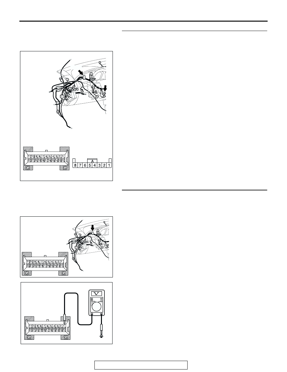
STEP 4. Check the wiring harness between combination 
meter connector C-101 (terminal 19) and immobilizer-ECU 
connector C-124 (terminal 5).

Q: Is the wiring harness between combination meter 

connector C-101 (terminal 19) and immobilizer-ECU 
connector C-124 (terminal 5) in good condition?
YES : 
Go to Step 5.
NO :  Repair the wiring harness. Confirm the immobilizer 

indicator light illuminate normally.

STEP 5. Measure the voltage at combination meter 
connector C-101 in order to check the battery circuit of 
power supply system to the combination meter.
(1) Turn the ignition switch to the "OFF" (LOCK) position.

(2) Disconnect combination meter connector C-101, and 

measure at the wiring harness side.

(3) Measure the voltage between terminal 1 and ground.

• The measured value should be approximately 12 volts 

(battery positive voltage).

Q: Does the measured voltage correspond with this range?

YES : Go to Step 8.
NO :  Go to Step 6.

AC305232

CONNECTORS: C-101, C-124

C-124

C-124

HARNESS SIDE

AX

C-101

HARNESS SIDE

C-101

AC305231CT

CONNECTOR: C-101

HARNESS SIDE

AC209365

CONNECTOR C-101 
(HARNESS SIDE)

HT

IGNITION SWITCH

TSB Revision

CHASSIS ELECTRICAL

54A-36

STEP 6. Check combination meter connector C-101 for 
loose, corroded or damaged terminals, or terminals 
pushed back in the connector.

Q: Is combination meter connector C-101 in good 

condition?
YES : 
Go to Step 7.
NO :  Repair or replace the component(s). Refer to GROUP 

00E, Harness Connector Inspection 

P.00E-2

. Confirm 

the immobilizer indicator light illuminate normally.

STEP 7. Check the wiring harness between combination 
meter connector C-101 (terminal 1) and the battery.

NOTE: Also check intermediate connector C-29 and joint con-
nector C-01 for loose, corroded, or damaged terminals, or ter-
minals pushed back in the connector. If intermediate connector 
C-29 or joint connector C-01 is damaged, repair or replace it. 
Refer to GROUP 00E, Harness Connector Inspection 

P.00E-2

.

Q: Is the wiring harness between combination meter 

connector C-101 (terminal 1) and the battery in good 
condition?
YES : 
Go to Step 8.
NO :  Repair the wiring harness. Check to see that all 

meters operate.

AC305231CT

CONNECTOR: C-101

HARNESS SIDE

AC305232

CONNECTORS: C-01, C-29, C-101

C-124

AY

C-01

HARNESS SIDE

C-101

C-29

C-29

C-01

IGNITION SWITCH

TSB Revision

CHASSIS ELECTRICAL

54A-37

STEP 8. Retest the system.
Q: Is the malfunction eliminated?

YES : The procedure is complete. (If no malfunctions are 

found in all steps, an intermittent malfunction is 
suspected. Refer to GROUP 00, How to Use 
Troubleshooting/Inspection Service Point 

P.00-6

).

NO :  Replace the combination meter.

DATA LIST REFERENCE TABLE

M1543007300325

CHECK AT IMMOBILIZER-ECU 

M1543007600508

Terminal Voltage Check

MUT-III
SCAN TOOL
DISPLAY

ITEM 
NO.

INSPECTION ITEM

INSPECTION
REQUIREMENT

NORMAL 
CONDITION

REGD.KEY

01

Key has been registered -

Number of registered ignition 
keys

TP LOCK CHECK

02

Determining whether the 
ignition key can be 
registered or not

UNLOCK

Can be overwritten (Correct)

LOCK

Can not be overwritten 
(Incorrect)

AC307447

TERMINAL NO.

SIGNAL

CHECKING 
REQUIREMENT

TERMINAL VOLTAGE

1

Immobilizer-ECU power 
supply

Ignition switch: "LOCK" 
(OFF) 

0V

Ignition switch: "ON" 

Battery positive voltage

2

Immobilizer-ECU ground Always

0V

3

powertrain control 
module

-

-

5

Immobilizer indicator 
light

When immobilizer 
indicator light is 
illuminated

Approximately 5 volts

When immobilizer 
indicator light is not 
illuminated

0V

7

Ignition key ring antenna −

8

Ignition key ring antenna −

IGNITION SWITCH

TSB Revision

CHASSIS ELECTRICAL

54A-38

SPECIAL TOOLS

M1543000601760

TOOL

TOOL NUMBER 
AND NAME

REPLACED BY 
MILLER TOOL 
NUMBER

APPLICATION

MB991958

A: MB991824
B: MB991827
C: MB991910
D: MB991911
E: MB991914
F: MB991825
G: MB991826

MUT-III sub assembly

A: Vehicle 

communication 
interface (V.C.I.)

B: MUT-III USB cable
C: MUT-III main 

harness A 
(Vehicles with CAN 
communication 
system)

D: MUT-III main 

harness B 
(Vehicles without 
CAN 
communication 
system)

E: MUT-III main 

harness C (for 
daimler chrysler 
models only)

F: MUT-III 

measurement 
adapter Harness

G: MUT-III trigger 

harness

MB991824-KIT
NOTE: G: MB991826 
MUT-III Trigger Harness 
is not necessary when 
pushing V.C.I. ENTER 
key.

Reading diagnostic 
trouble code

CAUTION

MUT-III main harness A 
(MB991910) should be 
used. MUT-III main 
harness B and C 
should not be used for 
this vehicle.

MB991910

MB991826

MB991958

MB991911

MB991914

MB991824

MB991827

MB991825

DO NOT USE

A

B

C

D

E

F

G

DO NOT USE


Content   ..  1446  1447  1448  1449   ..