Mitsubishi Galant (2004+). Manual - part 1447


  Index      Mitsubishi     Mitsubishi Galant - service repair manual 2004 year


Search            


Content   ..  1445  1446  1447  1448   ..


Mitsubishi Galant (2004+). Manual - part 1447


IGNITION SWITCH

TSB Revision

CHASSIS ELECTRICAL

54A-31

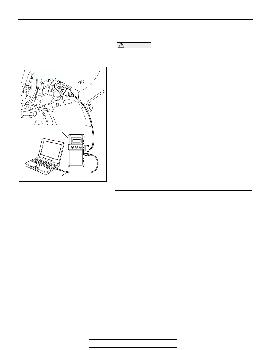
STEP 3. Using scan tool MB991958, read the MFI system 
diagnostic trouble code.

CAUTION

To prevent damage to scan tool MB991958, always turn the 
ignition switch to "LOCK" (OFF) position before connect-
ing or disconnecting scan tool.
(1) Connect scan tool MB991958 to the data link connector.
(2) Turn the ignition switch "ON" position.
(3) Read the diagnosis code.
Q: Have any MFI system DTCs set?

Yes :  Refer to GROUP 13A, MFI Diagnosis 

− Diagnostic 

Trouble Code Chart 

P.13A-753

 or GROUP 13B, MFI 

Diagnosis 

− Diagnostic Trouble Code Chart 

P.13B-796

.

No :  Go to Step 4.

STEP 4. Attempt to start the engine.
Q: Does the engine start?

YES : The procedure is complete (If no malfunctions are 

found in all steps, an intermittent malfunction is 
suspected. Refer to GROUP 00, How to Use 
Troubleshooting/Inspection Service Points-How to 
Cope with Intermittent Malfunction 

P.00-6

).

NO :  Refer to GROUP 13A, MFI Diagnosis 

− Symptom 

Chart 

P.13A-38

 or GROUP 13B, MFI Diagnosis 

− 

Symptom Chart 

P.13B-37

. If the malfunction is not 

resolved, replace the immobilizer-ECU. Then register 
the password (secret code) and encrypted code. 
(Refer to 

P.54A-40

.) The engine should now start.

AC305412

AB

MB991910

DATA LINK

CONNECTOR

MB991824

MB991827

IGNITION SWITCH

TSB Revision

CHASSIS ELECTRICAL

54A-32

INSPECTION PROCEDURE 4: The Immobilizer Indicator Light does not Illuminate.

BATTERY

RELAY 
BOX

JOINT
CONNECTOR (1)

COMBINATION
METER

IMMOBILIZER
-ECU

IMMOBILIZER

Immobilizer Indicator Light Circuit

IGNITION SWITCH

TSB Revision

CHASSIS ELECTRICAL

54A-33

.

CIRCUIT OPERATION
If the requirements for starting the engine are not sat-
isfied, the immobilizer-ECU flashes the immobilizer 
indicator for 30 seconds.

.

TECHNICAL DESCRIPTION (COMMENT)
The immobilizer indicator light or a malfunction of the 
combination meter or immobilizer-ECU.

.

TROUBLESHOOTING HINTS

• Malfunction of combination meter 

• Malfunction of immobilizer-ECU

• The wiring harness or connectors may have 

loose, corroded, or damaged terminals, or termi-
nals pushed back in the connector

.

DIAGNOSIS

Required Special Tool:

• MB991223: Harness Set 

STEP 1. Check immobilizer-ECU connector C-124 for 
loose, corroded or damaged terminals, or terminals 
pushed back in the connector

Q: Is immobilizer-ECU connector C-124 in good condition?

YES : Go to Step 2.
NO :  Repair or replace the component(s). Refer to GROUP 

00E, Harness Connector Inspection 

P.00E-2

. Confirm 

that scan tool MB991958 communicates normally.

AC305231

C-29

CONNECTORS: C-01, C-29, C-101, C-124

C-01

C-124

C-101

CU

AC305231CQ

CONNECTOR: C-124

HARNESS SIDE

IGNITION SWITCH

TSB Revision

CHASSIS ELECTRICAL

54A-34

STEP 2. Check the immobilizer indicator light circuit of 
immobilizer-ECU connector C-124.

(1) Disconnect the immobilizer-ECU connector C-124 and 

measure at the harness side.

(2) Turn the ignition switch to the "ON" position.

(3) Connect terminal 5 to the ground.
Q: Does only the immobilizer indicator light illuminate? 

(other indicator lights are in good condition)
YES : 
Replace the immobilizer-ECU. Then register the 

password (secret code) and encrypted code 

P.54A-40

.

NO :  Go to Step 3.

STEP 3. Check immobilizer-ECU connector C-124 and 
combination meter connector C-101 for loose, corroded or 
damaged terminals, or terminals pushed back in the 
connector.

Q: Are immobilizer-ECU connector C-124 and combination 

meter connector C-101 in good condition?
YES : 
Go to Step 4.
NO :  Repair or replace the component(s). Refer to GROUP 

00E, Harness Connector Inspection 

P.00E-2

. Confirm 

the immobilizer indicator light illuminate normally.

AC305231CQ

CONNECTOR: C-124

HARNESS SIDE

AC306468

AC306468

CONNECTOR C-124 
(HARNESS SIDE)

AG

AC305232

CONNECTORS: C-101, C-124

C-124

C-124

HARNESS SIDE

AX

C-101

HARNESS SIDE

C-101


Content   ..  1445  1446  1447  1448   ..