Mitsubishi Galant (2004+). Manual - part 1442


  Index      Mitsubishi     Mitsubishi Galant - service repair manual 2004 year


Search            


Content   ..  1440  1441  1442  1443   ..


Mitsubishi Galant (2004+). Manual - part 1442


IGNITION SWITCH

TSB Revision

CHASSIS ELECTRICAL

54A-11

DIAGNOSIS FUNCTION

M1543007000443

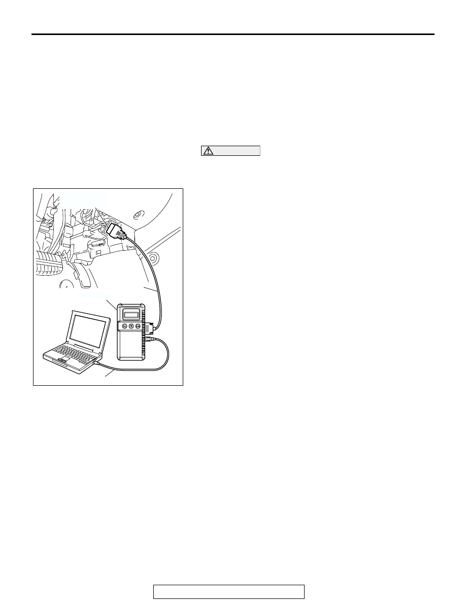
HOW TO CONNECT SCAN TOOL (MUT-III)

Required Special Tools:

• MB991958: Scan Tool (MUT-III Sub Assembly)

• MB991824: Vehicle Communication Interface (V.C.I.)

• MB991827: MUT-III USB Cable

• MB991910: MUT-III Main Harness A (Vehicles with CAN 

communication system) (Vehicles with CAN communi-
cation system)

CAUTION

To prevent damage to scan tool MB991958, always turn the 
ignition switch to the "LOCK" (OFF) position before con-
necting or disconnecting scan tool MB991958.
1. Ensure that the ignition switch is at the "LOCK" (OFF) 

position.

2. Start up the personal computer.
3. Connect special tool MB991827 to special tool MB991824 

and the personal computer.

4. Connect special tool MB991910 to special tool MB991824.
5. Connect special tool MB991910 to the data link connector.
6. Turn the power switch of special tool MB991824 to the "ON" 

position.
NOTE: When special tool MB991824 is energized, special 
tool MB991824 indicator light will be illuminated in a green 
color.

7. Start the MUT-III system on the personal computer.

NOTE: Disconnecting the scan tool MB991958 is the 
reverse of the connecting sequence, making sure that the 
ignition switch is at the "LOCK" (OFF) position.

AC305412

AB

MB991910

DATA LINK

CONNECTOR

MB991824

MB991827

IGNITION SWITCH

TSB Revision

CHASSIS ELECTRICAL

54A-12

HOW TO READ AND ERASE DIAGNOSTIC 
TROUBLE CODES

Required Special Tools:

• MB991958: Scan Tool (MUT-III Sub Assembly)

• MB991824: Vehicle Communication Interface (V.C.I.)

• MB991827: MUT-III USB Cable

• MB991910: MUT-III Main Harness A (Vehicles with CAN 

communication system) (Vehicles with CAN communi-
cation system)

CAUTION

To prevent damage to scan tool MB991958, always turn the 
ignition switch to the "LOCK" (OFF) position before con-
necting or disconnecting scan tool MB991958.
NOTE: If the battery voltage is low, diagnostic trouble codes will 
not be set. Check the battery if scan tool MB991958 does not 
display.
1. Connect scan tool MB991958 to the data link connector.
2. Turn the ignition switch to "ON" position.
3. Select "Interactive Diagnosis" from the start-up screen.
4. Select "System select."
5. Choose "IMMOBILIZER" from the "POWER TRAIN" tab.
6. Select "Self-diagnosis."
7. If a DTC is set, it is shown.
8. Choose "Erase DTCs" to erase the DTC.

AC305412

AB

MB991910

DATA LINK

CONNECTOR

MB991824

MB991827

IGNITION SWITCH

TSB Revision

CHASSIS ELECTRICAL

54A-13

HOW TO READ DATA LIST

Required Special Tools:

• MB991958: Scan Tool (MUT-III Sub Assembly)

• MB991824: Vehicle Communication Interface (V.C.I.)

• MB991827: MUT-III USB Cable

• MB991910: MUT-III Main Harness A (Vehicles with CAN 

communication system) (Vehicles with CAN communi-
cation system)

CAUTION

To prevent damage to scan tool MB991958, always turn the 
ignition switch to the "LOCK" (OFF) position before con-
necting or disconnecting scan tool MB991958.
1. Connect scan tool MB991958 to the data link connector.
2. Turn the ignition switch to "ON" position.
3. Select "Interactive Diagnosis" from the start-up screen.
4. Select "System select."
5. Choose "IMMOBILIZER" from the "POWER TRAIN" tab.
6. Select "Data List."
7. Choose an appropriate item and select the "OK" button.

DIAGNOSTIC TROUBLE CODE CHART

M1543007100439

CAUTION

During diagnosis, a DTC code associated with 
other system may be set when the ignition switch 
is turned on with connector(s) disconnected. On 
completion, confirm all systems for DTC code(s). 
If DTC code(s) are set, erase them all.
Use the following chart to develop proper diagnostic 
strategy.

AC305412

AB

MB991910

DATA LINK

CONNECTOR

MB991824

MB991827

DIAGNOSTIC 
TROUBLE CODE NO. 

DESCRIPTION

REFERENCE PAGE

11

Transponder communication system or radio interference 
of encrypted code.

P.54A-14

12

Encrypted codes are not the same or not registered.

P.54A-17

IGNITION SWITCH

TSB Revision

CHASSIS ELECTRICAL

54A-14

DIAGNOSTIC TROUBLE CODE PROCEDURES

DTC 11: Transponder Communication System or Radio Interference of Encrypted Code.

.

CIRCUIT OPERATION
The ignition key is powered by the ignition key ring 
antenna. The ignition key then sends an encrypted 
code. The ignition key ring antenna receives the 
encrypted code, and determines if the ignition key is 
registered.

.

DTC SET CONDITION

• DTC 11 may be output if other ignition keys are in 

the vicinity of the vehicle as it is being started.

• The transponder’s encrypted code is not sent to 

the immobilizer-ECU immediately after the igni-
tion switch is turned to "ON" position.

NOTE: DTC 11 is always output together with MFI 
system DTC P0513.

.

TROUBLESHOOTING HINTS

• Radio interference of the encrypted code

• Malfunction of the transponder

• Malfunction of the immobilizer-ECU.

IMMOBILIZER-
ECU

KEY
REMINDER
SWITCH

IGNITION
KEY RING
ANTENNA

IGNITION KEY

TRANSPONDER

HIGH FREQUENCY
CIRCUIT

Ignition Key Ring and Immobilizer-ECU Circuit

AC305231CR

CONNECTOR: C-124

AC305235

CONNECTOR: C-310

AD


Content   ..  1440  1441  1442  1443   ..