Content .. 1414 1415 1416 1417 ..
Mitsubishi Galant (2004+). Manual - part 1416
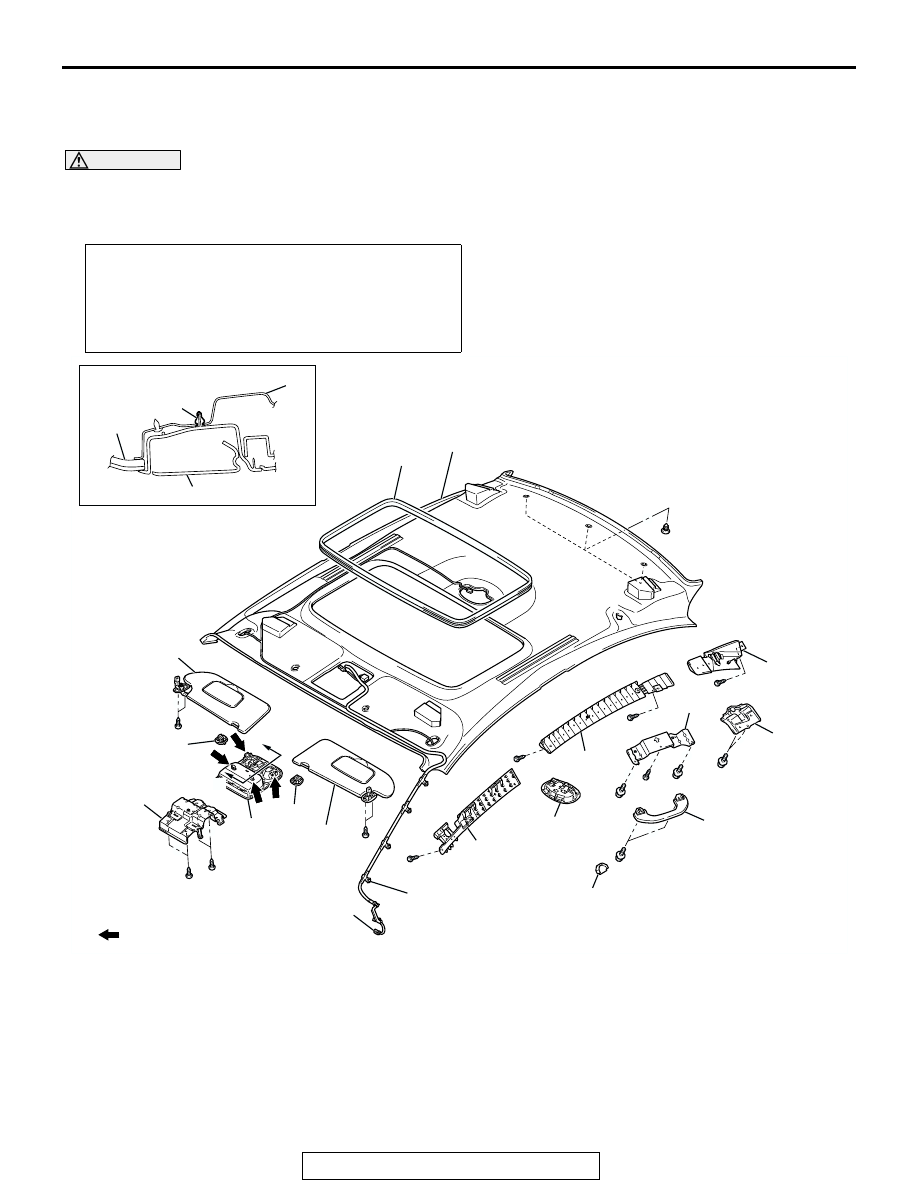
HEADLINING
TSB Revision
INTERIOR
52A-19
HEADLINING
REMOVAL AND INSTALLATION
M1521001400360
WARNING
When removing and installing the front passenger seat, be sure to carry out accuracy check
occupant classification sensor after the seat has been installed in the vehicle. (Refer to
GROUP 52B, On-Vehicle Service
.)
Pre-removal and Post-installation Operation
• Front Seat Assembly (Refer to
• Removal and Installation of Rear Seat Cushion Assembly
and Rear Seatback Assembly (Refer to
• Removal and Installation of Front Pillar Trim, Center Pillar
Trim Upper and Rear Pillar Trim (Refer to
AC307811
NOTE
: CLIP POSITION
SECTION A – A
11
1
2
3
2
1
12
4
13
6
15
16
14
7
10
10
3
CLIP
AB
5
11
A
A
8
9
REMOVAL STEPS
1.
SUN VISOR
2.
SUN VISOR HOLDER
3.
OVERHEAD CONSOLE
ASSEMBLY
4.
DOME LIGHT ASSEMBLY (REFER
TO GROUP 54A, DOME LIGHT
5.
ASSIST GRIP PLUG
6.
ROOF INSIDE ASSIST GRIP
<VEHICLES WITH ROOF INSIDE
ASSIST GRIP>
7.
SUNROOF OPENING TRIM
<VEHICLES WITH SUNROOF>
8.
ROOF HARNESS CLAMP
•
INSTRUMENT PANEL SIDE
COVER (REFER TO
9.
ROOF HARNESS CONNECTOR
REMOVAL STEPS (Continued)