Mitsubishi Galant (2004+). Manual - part 139
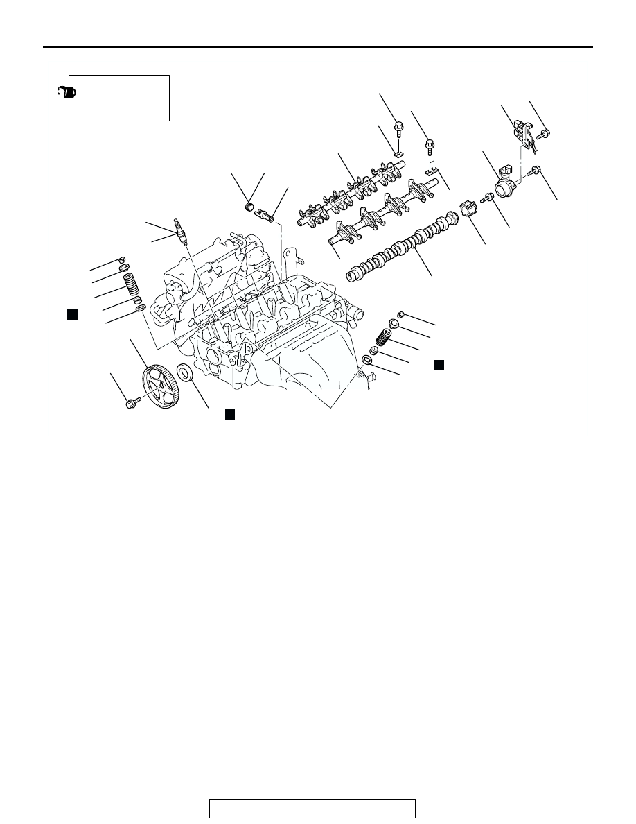
CAMSHAFT AND VALVE STEM SEAL
TSB Revision
ENGINE MECHANICAL <2.4L ENGINE>
11A-29
Required Special Tools:
• MB990767: Front Hub and Flange Yoke Holder
• MD998713: Camshaft Oil Seal Installer
• MD998719: Pin
• MD998772: Valve Spring Compressor
• MD998774: Valve Stem Seal Installer
AC306536AB
18
17
16
15
14
13
12
28*
27*
26*
25*
24*
23
22
21
19
20
N
28*
25*
24*
11 ± 1 N·m
98 ± 8 in-lb
22 ± 4 N·m
16 ± 3 ft-lb
13 ± 1 N·m
115 ± 9 in-lb
31 ± 3 N·m
23 ± 2 ft-lb
47 ± 7 N·m
35 ± 5 ft-lb
25 ± 4 N·m
18 ± 3 ft-lb
89 ± 9 N·m
65 ± 7 ft-lb
N
N
APPLY ENGINE OIL
TO ALL MOVING
PARTS BEFORE
INSTALLATION.
11
14 ± 1 N·m
120 ± 13 in-lb
29*
29*
CAMSHAFT REMOVAL STEPS
11.
CONNECTOR BRACKET
>>I<<
12.
CAMSHAFT POSITION SENSOR
SUPPORT
13.
CAMSHAFT POSITION SENSING
CYLINDER
<<A>>
>>H<<
14.
CAMSHAFT SPROCKET
>>G<<
15.
CAMSHAFT OIL SEAL
>>F<<
16.
EXHAUST ROCKER ARM SHAFT
CAPS
<<B>>
>>F<<
17.
EXHAUST ROCKER ARM AND
SHAFT ASSEMBLY
>>E<<
18.
INTAKE ROCKER ARM SHAFT CAPS
<<B>>
>>E<<
19.
INTAKE ROCKER ARM AND SHAFT
ASSEMBLY
<<C>>
>>D<<
20.
CAMSHAFT
•
WATER INLET FITTING AND
THERMOSTAT CASE ASSEMBLY
(REFER TO GROUP 14, WATER
HOSE AND WATER PIPE
21.
CYLINDER HEAD PLUG
22.
ENGINE OIL CONTROL VALVE
FILTER
VALVE STEM SEAL REMOVAL
STEPS
1.
CONTROL WIRING HARNESS
CONNECTION
2.
ROCKER COVER PCV HOSE
CONNECTION
3.
ROCKER COVER BREATHER HOSE
CONNECTION
7.
ROCKER COVER ASSEMBLY
8.
ROCKER COVER GASKET
9.
SPARK PLUG GUIDE OIL SEALS
16. EXHAUST ROCKER ARM SHAFT
CAPS
<<B>>
17. EXHAUST ROCKER ARM AND
SHAFT ASSEMBLY
>>E<<
18. INTAKE ROCKER ARM SHAFT CAPS
<<B>>
>>E<<
19. INTAKE ROCKER ARM AND SHAFT
ASSEMBLY
23. SPARK PLUGS
<<D>>
>>C<<
24. VALVE SPRING RETAINER LOCKS
25. VALVE SPRING RETAINERS
>>B<<
26. INTAKE VALVE SPRINGS
>>B<<
27. EXHAUST VALVE SPRINGS
>>A<<
28. VALVE STEM SEALS
29. VALVE SPRING SEATS