Mitsubishi Galant (2004+). Manual - part 1371


  Index      Mitsubishi     Mitsubishi Galant - service repair manual 2004 year


Search            


Content   ..  1369  1370  1371  1372   ..


Mitsubishi Galant (2004+). Manual - part 1371


DOOR MIRROR

TSB Revision

EXTERIOR

51-29

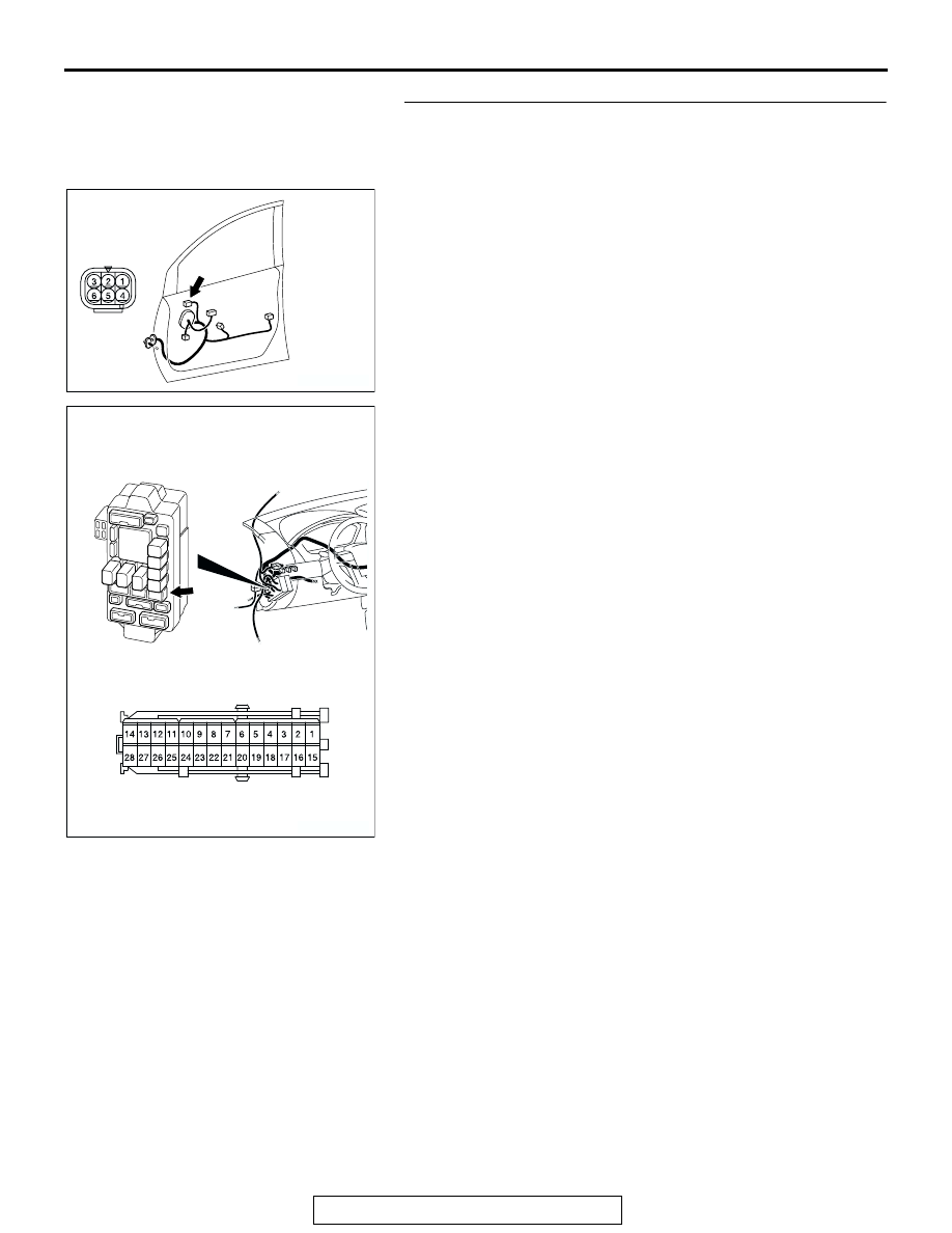
STEP 2. Check the remote controlled mirror (RH) 
connector E-01 and junction block connector C-211 for 
loose, corroded or damaged terminals, or terminals 
pushed back in the connector.

Q: Are the remote controlled mirror (RH) connector E-01 

and junction block connector C-211 in good condition?
YES : 
Go to Step 3.
NO :  Repair or replace the damaged component(s). Refer 

to GROUP 00E, Harness Connector Inspection 

P.00E-2

. Check if the door mirrors works normally.

AC307124

E-01 (GR)

CONNECTOR: E-01

HARNESS SIDE

AC

AC307123

JUNCTION BLOCK (FRONT VIEW)

CONNECTOR: C-211

AB

DOOR MIRROR

TSB Revision

EXTERIOR

51-30

STEP 3. Check the wiring harness between the remote 
controlled mirror (RH) connector E-01 (terminal 1) and 
junction block connector C-211 (terminal 3).

NOTE: Also check intermediate connector C-12 for loose, cor-
roded or damaged terminals, or terminals pushed back in the 
connector. If intermediate connector C-12 is damaged, repair or 
replace the damaged component(s) as described in GROUP 
00E, Harness Connector Inspection 

P.00E-2

.

Q: Is the wiring harness between remote controlled mirror 

(RH) connector E-01 (terminal 1) and junction block 
connector C-211 (terminal 3) in good condition?
YES : 
Go to step 4.
NO :  Repair the wiring harness as necessary. Check if the 

all heated door mirrors work normally.

AC307124

E-01 (GR)

CONNECTOR: E-01

HARNESS SIDE

AC

AC307123

JUNCTION BLOCK (FRONT VIEW)

CONNECTOR: C-211

AB

AC307120

CONNECTOR: C-12

AB

DOOR MIRROR

TSB Revision

EXTERIOR

51-31

STEP 4. Check remote controlled mirror (LH) connector 
E-09.

Q: Is remote controlled mirror (LH) connector E-09 in good 

condition?
YES : 
Go to Step 5.
NO :  Repair or replace the damaged component(s). Check 

if the all heated door mirrors works normally.

STEP 5. Check the wiring harness between remote 
controlled mirror (LH) connector E-09 (terminal 1) and 

junction block connector C-211 (terminal 3).

AC307125

E-09 (GR)

CONNECTOR: E-09

HARNESS SIDE

AC

AC307125

E-09 (GR)

CONNECTOR: E-09

HARNESS SIDE

AC

AC307123

JUNCTION BLOCK (FRONT VIEW)

CONNECTOR: C-211

AB

DOOR MIRROR

TSB Revision

EXTERIOR

51-32

NOTE: Also check intermediate connector C-26 for loose, cor-
roded or damaged terminals, or terminals pushed back in the 
connector. If intermediate connector C-26 is damaged, repair or 
replace the damaged component(s) as described in GROUP 
00E, Harness Connector Inspection 

P.00E-2

.

Q: Is the wiring harness between remote controlled mirror 

(RH) connector E-09 (terminal 1) and junction block 
connector C-211 (terminal 3) in good condition?
YES : 
The procedure is complete.
NO :  Repair the wiring harness as necessary. Check if the 

all heated door mirrors work normally.

INSPECTION PROCEDURE 2: Right or Left Heated Door Mirror does not Operate

AC307120

CONNECTOR: C-12

AB

JUNCTION 
BLOCK

DEFOGGER 
RELAY

DEFOGGER

REMOTE 
CONTROLLED 
MIRROR (LH)

REMOTE 
CONTROLLED 
MIRROR (RH)

MIRROR 
HEATER

MIRROR 
HEATER

Heated door mirror Circuit


Content   ..  1369  1370  1371  1372   ..