Mitsubishi Galant (2004+). Manual - part 1194


  Index      Mitsubishi     Mitsubishi Galant - service repair manual 2004 year


Search            


Content   ..  1192  1193  1194  1195   ..


Mitsubishi Galant (2004+). Manual - part 1194


MULTIPORT FUEL INJECTION (MFI) DIAGNOSIS

TSB Revision

MULTIPORT FUEL INJECTION (MFI) <3.8L ENGINE>

13B-469

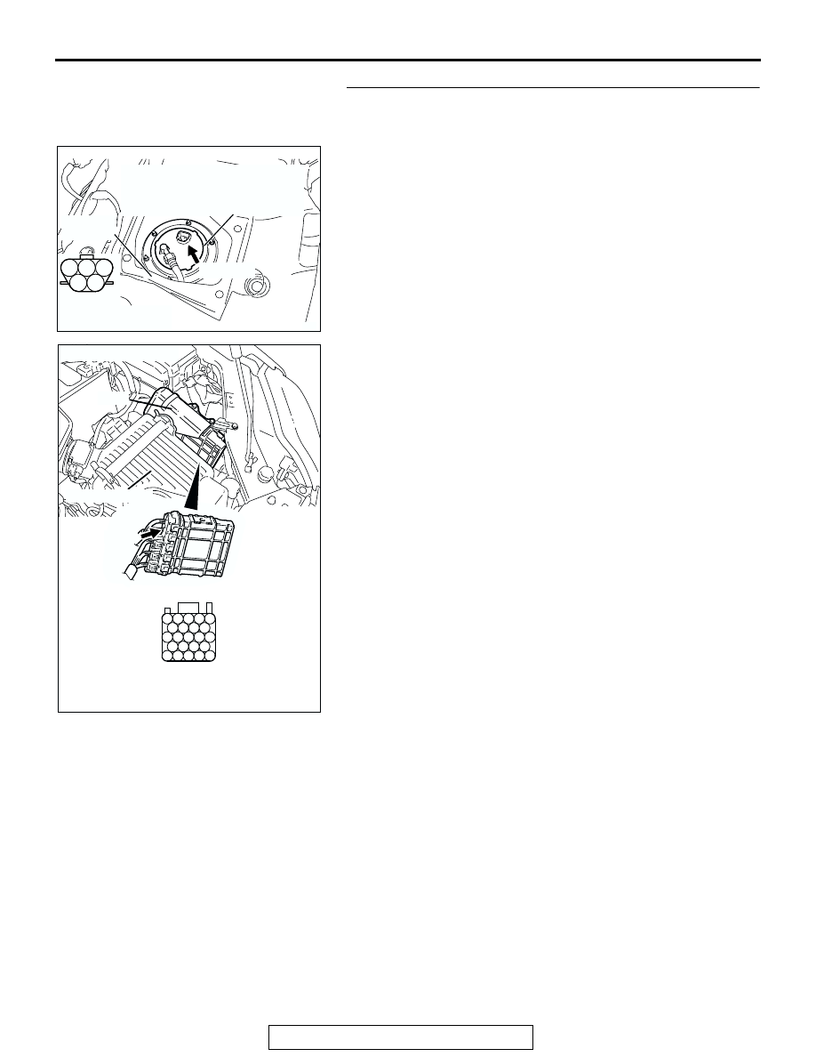
STEP 10. Check for open circuit and harness damage 
between fuel tank temperature sensor connector D-18 and 
PCM connector B-20.

NOTE: Check harness after checking intermediate connector 
C-25. If the intermediate connector is damaged, repair or 
replace it. Refer to GROUP 00E, Harness Connector Inspec-
tion 

P.00E-2

. Then go to Step 11.

Q: Is the harness wire in good condition?

YES : Replace the PCM. Then go to Step 11.
NO :  Repair it. Then go to Step 11.

1

2

3

4

5

AK303088

HARNESS
CONNECTOR:
COMPONENT SIDE

SERVICE
HOLE

AB

FUEL PUMP MODULE
(INCORPORATING FUEL LEVEL
SENSOR (MAIN) AND FUEL
TANK TEMPERATURE SENSOR)

CONNECTOR: D-18

D-18 (GR)

AK303092

25

21

24 23 22

29 28 27 26

34 33 32 31 30

38 37 36 35

43 42 41 40 39

CONNECTOR: B-20

B-20

PCM

AB

HARNESS CONNECTOR: 
COMPONENT SIDE

AIR CLEANER

MULTIPORT FUEL INJECTION (MFI) DIAGNOSIS

TSB Revision

MULTIPORT FUEL INJECTION (MFI) <3.8L ENGINE>

13B-470

STEP 11. Test the OBD-II drive cycle.

(1) Carry out a test drive with the drive cycle pattern. Refer to 

Diagnostic Function 

− OBD-II Drive Cycle − Procedure 6 − 

Other Monitor 

P.00E-2

.

(2) Check the diagnostic trouble code (DTC).
Q: Is DTC P0183 set?

YES : Retry the troubleshooting.
NO :  The inspection is complete.

Continue

MULTIPORT FUEL INJECTION (MFI) DIAGNOSIS

TSB Revision

MULTIPORT FUEL INJECTION (MFI) <3.8L ENGINE>

13B-471

13B

DTC P0201: Injector Circuit Malfunction - Cylinder 1

CAUTION

If DTC P0201 has been set, TCL related DTC 
U1120 is also set. After P0201 has been diag-
nosed, don't forget to erase DTC U1120.

AK302849

YELLO

W

-

BLUE

YELLO

W

-

BLUE

RED

RED

RED-

WHITE

RED-

WHITE

RED-

WHITE

BATTERY

MFI
RELAY

B-17X

INJECTOR
NO. 1

4

1

2

3

1

2

153

5

9

POWERTRAIN CONTROL
MODULE (PCM)

     B-32
MU802645

      B-23

B-01

2

1

Injector Circuit - Cylinder 1

3 4

1 2

1

2 3

6

7 8

4 5

9 10

121 122 123 124 125 126 127

128 129 130 131 132 133

134 135 136 137 138 139 140

141 142 143 144 145 146

147 148 149 150 151 152 153

MULTIPORT FUEL INJECTION (MFI) DIAGNOSIS

TSB Revision

MULTIPORT FUEL INJECTION (MFI) <3.8L ENGINE>

13B-472

.

CIRCUIT OPERATION

• The injector power is supplied from the MFI relay 

(terminal No. 4).

• The PCM controls the injector by turning the 

power transistor in the PCM "ON" and "OFF".

.

TECHNICAL DESCRIPTION

• The amount of fuel injected by the injector is con-

trolled by the amount of continuity time the coil is 
grounded by the PCM.

• A surge voltage is generated when the injectors 

are driven and the current flowing to the injector 
coil is shut off.

• The PCM checks this surge voltage.

.

DESCRIPTIONS OF MONITOR METHODS
Off-surge does not occur after injector is operated.

.

MONITOR EXECUTION
Continuous

.

MONITOR EXECUTION CONDITIONS (Other 
monitor and Sensor)

Other Monitor (There is no temporary DTC stored 

in memory for the item monitored below)

• Not applicable

Sensor (The sensor below is determined to be 

normal)

• Not applicable

.

AK303096

CONNECTOR: B-01

AB

B-01 (GR)

1

2

3

4

1

2

3

4

1

2

3

4

1

2

3

4

AK303014

CONNECTOR: B-17X

MFI RELAY

MFI RELAY

FRONT OF VEHICLE

B-17X

AB

AK303097

CONNECTOR: B-32

AB

B-32 (B)

AK303059

CONNECTOR: B-23

PCM

AB

AIR CLEANER

B-23


Content   ..  1192  1193  1194  1195   ..