Content .. 1190 1191 1192 1193 ..
Mitsubishi Galant (2004+). Manual - part 1192
MULTIPORT FUEL INJECTION (MFI) DIAGNOSIS
TSB Revision
MULTIPORT FUEL INJECTION (MFI) <3.8L ENGINE>
13B-461
.
CIRCUIT OPERATION
• 5-volt voltage is applied to the fuel tank tempera-
ture sensor output terminal (terminal No. 3) from
the PCM (terminal No. 41) via the resistor in the
PCM.
• The fuel tank temperature sensor output voltage
increases when the resistance increases and
decreases when the resistance decreases. The
ground terminal (terminal No. 1) is grounded to
the vehicle body.
.
TECHNICAL DESCRIPTION
• The fuel tank temperature sensor converts the
fuel tank temperature to a voltage.
• The PCM detects the fuel tank temperature with
this output voltage.
.
DESCRIPTIONS OF MONITOR METHODS
Fuel tank temperature sensor output voltage is out of
specified range.
.
MONITOR EXECUTION
Continuous
.
MONITOR EXECUTION CONDITIONS (Other
monitor and Sensor)
Other Monitor (There is no temporary DTC stored
in memory for the item monitored below)
• Not applicable
Sensor (The sensor below is determined to be
normal)
• Engine coolant temperature sensor
• Intake air temperature sensor
.
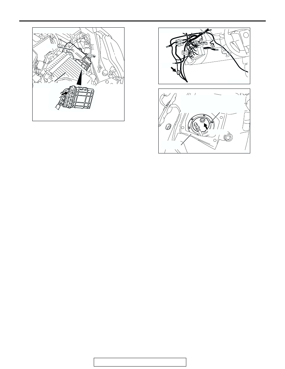
AK303085
CONNECTOR: B-20
PCM
AB
AIR CLEANER
B-20
AK303086
CONNECTOR: C-25
C-25
AB
AK303087
SERVICE
HOLE
AB
FUEL PUMP MODULE
(INCORPORATING FUEL LEVEL
SENSOR (MAIN) AND FUEL
TANK TEMPERATURE SENSOR)
CONNECTOR: D-18
D-18 (GR)