Content .. 1147 1148 1149 1150 ..
Mitsubishi Galant (2004+). Manual - part 1149
MULTIPORT FUEL INJECTION (MFI) DIAGNOSIS
TSB Revision
MULTIPORT FUEL INJECTION (MFI) <3.8L ENGINE>
13B-289
MONITOR EXECUTION CONDITIONS (Other
monitor and Sensor)
Other Monitor (There is no temporary DTC stored
in memory for the item monitored below)
• Not applicable
Sensor (The sensor below is determined to be
normal)
• Engine coolant temperature sensor
.
DTC SET CONDITIONS
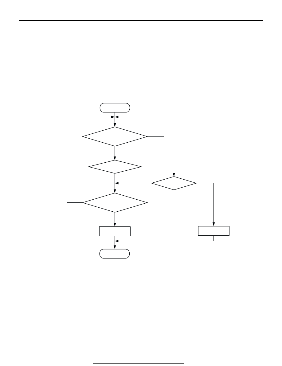
Logic Flow Chart
.
Check Conditions
• 60 seconds have elapsed from the start of the
previous monitoring.
• Engine coolant temperature is higher than 20°C
(68
°F).
• While the right bank heated oxygen sensor (rear)
heater is on.
• Battery positive voltage is at between 11 and 16.5
volts.
Judgment Criteria
• The right bank heated oxygen sensor (rear)
heater current has continued to be lower than
0.16 ampere or higher than 5.0 ampere for 4 sec-
onds.
.
OBD-II DRIVE CYCLE PATTERN
Refer to Diagnostic Function
− OBD-II Drive Cycle −
Procedure 6
.
.
START
END
YES
YES
YES
YES
NO
NO
NO
NO
MALFUNCTION
GOOD
CONTINUOUS
FAILURE FOR 4secs
MONITORING
CONDITIONS
CURRENT < 0.16A
CURRENT > 5.0A
AK302401