Content .. 1145 1146 1147 1148 ..
Mitsubishi Galant (2004+). Manual - part 1147
MULTIPORT FUEL INJECTION (MFI) DIAGNOSIS
TSB Revision
MULTIPORT FUEL INJECTION (MFI) <3.8L ENGINE>
13B-281
.
CIRCUIT OPERATION
• A voltage corresponding to the oxygen concen-
tration in the exhaust gas is sent to the PCM (ter-
minal No. 97) from the output terminal (terminal
No. 4) of the right bank heated oxygen sensor
(rear).
• Terminal No. 2 of the right bank heated oxygen
sensor (rear) is grounded with PCM (terminal No.
69).
.
TECHNICAL DESCRIPTION
• The output signal of the right bank heated oxygen
sensor (front) is compensated by the output sig-
nal of the right bank heated oxygen sensor (rear).
• The PCM checks for an open circuit in the right
bank heated oxygen sensor (rear) output line.
.
DESCRIPTIONS OF MONITOR METHODS
Right bank heated oxygen sensor (rear) output volt-
age does not change during specified go/stop
operations including fuel cut are repeated.
.
MONITOR EXECUTION
Continuous
.
MONITOR EXECUTION CONDITIONS (Other
monitor and Sensor)
Other Monitor (There is no temporary DTC stored
in memory for the item monitored below)
• Heated oxygen sensor heater (front) monitor
• Heated oxygen sensor heater (rear) monitor
• Air/fuel ratio feedback monitor
Sensor (The sensor below is determined to be
normal)
• Mass airflow sensor
• Engine coolant temperature sensor
• Intake air temperature sensor
• Barometric pressure sensor
.
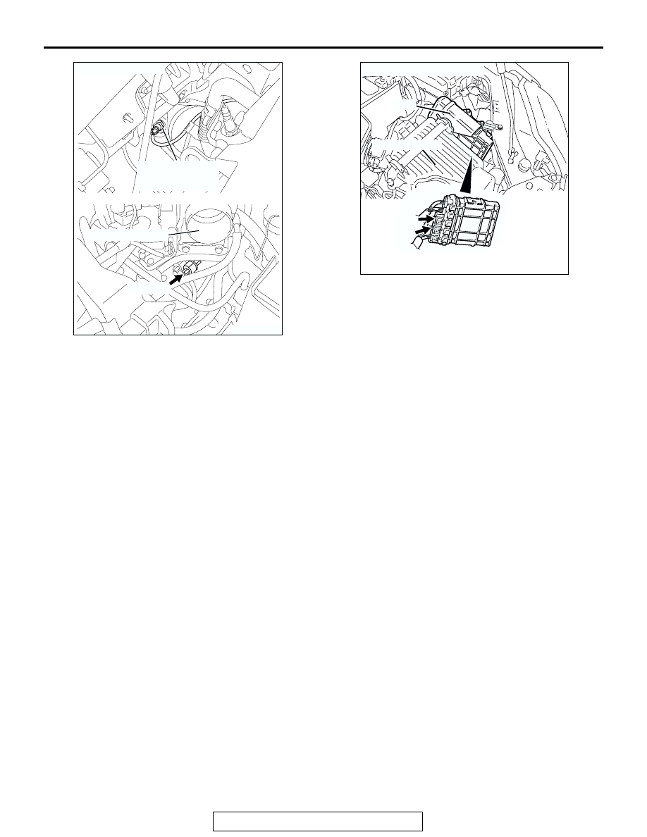
AK303063
THROTTLE BODY
RIGHT BANK
HEATED OXYGEN
SENSOR (REAR)
CONNECTOR: B-08
B-08 (GR)
AB
AK303013
CONNECTORS: B-21, B-22
PCM
AB
AIR CLEANER
B-22 (B)
B-21 (B)