Mitsubishi Galant (2004+). Manual - part 1126


  Index      Mitsubishi     Mitsubishi Galant - service repair manual 2004 year


Search            


Content   ..  1124  1125  1126  1127   ..


Mitsubishi Galant (2004+). Manual - part 1126


MULTIPORT FUEL INJECTION (MFI) DIAGNOSIS

TSB Revision

MULTIPORT FUEL INJECTION (MFI) <3.8L ENGINE>

13B-197

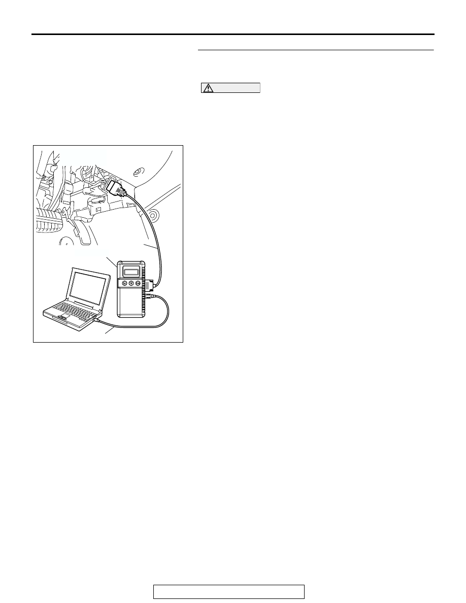
STEP 5. Using scan tool MB991958, check data list item 39: 
Right Bank Heated Oxygen Sensor Bank 1, Sensor 1 (right 
front).

CAUTION

To prevent damage to scan tool MB991958, always turn the 
ignition switch to the "LOCK" (OFF) position before con-
necting or disconnecting scan tool MB991958.
(1) Connect scan tool MB991958 to the data link connector.
(2) Start the engine and run at idle.
(3) Set scan tool MB991958 to the data reading mode for item 

39, Heated Oxygen Sensor Bank 1, Sensor 1 (right front).

• Warming up the engine. When the engine is revved, the 

output voltage should be 0.6 to 1.0 volt.

• Warming up the engine. When the engine is idling, the 

output voltage should repeat 0.4 volt and 0.6 to 1.0 volt 
alternately.

(4) Turn the ignition switch to the "LOCK" (OFF) position.
Q: Is the sensor operating properly?

YES : It can be assumed that this malfunction is intermittent. 

Refer to GROUP 00, How to Use 
Troubleshooting/Inspection Service Points 

P.00-6

.

NO :  Replace the PCM. Then go to Step 15.

AC305412

AB

MB991910

DATA LINK

CONNECTOR

MB991824

MB991827

MULTIPORT FUEL INJECTION (MFI) DIAGNOSIS

TSB Revision

MULTIPORT FUEL INJECTION (MFI) <3.8L ENGINE>

13B-198

STEP 6. Check harness connector B-09 at right bank 
heated oxygen sensor (front) and harness connector B-22 
at PCM for damage.
Q: Is the harness connector in good condition?

YES : Repair harness wire between right bank heated 

oxygen sensor (front) connector B-09 (terminal No. 4) 
and PCM connector B-22 (terminal No. 92) because 
of open circuit or harness damage. Then go to Step 
15.

NO :  Repair or replace it. Refer to GROUP 00E, Harness 

Connector Inspection 

P.00E-2

. Then go to Step 15. 

1

2

3

4

AK303048

B-09 (B)

CONNECTOR: B-09

THROTTLE BODY

RIGHT BANK
HEATED OXYGEN
SENSOR (FRONT)

AB

HARNESS
CONNECTOR:
COMPONENT SIDE

AK303016

104

96

94

95

93 92 91

99 98 97

103 102 101 100

108 107 106 105

113 112 111 110 109

CONNECTOR: B-22

B-22 (B)

PCM

AB

HARNESS CONNECTOR: 
COMPONENT SIDE

AIR CLEANER

MULTIPORT FUEL INJECTION (MFI) DIAGNOSIS

TSB Revision

MULTIPORT FUEL INJECTION (MFI) <3.8L ENGINE>

13B-199

STEP 7. Check harness connector B-09 at right bank 
heated oxygen sensor (front) for damage.
Q: Is the harness connector in good condition?

YES : Go to Step 8.
NO :  Repair or replace it. Refer to GROUP 00E, Harness 

Connector Inspection 

P.00E-2

. Then go to Step 15. 

1

2

3

4

AK303048

B-09 (B)

CONNECTOR: B-09

THROTTLE BODY

RIGHT BANK
HEATED OXYGEN
SENSOR (FRONT)

AB

HARNESS
CONNECTOR:
COMPONENT SIDE

MULTIPORT FUEL INJECTION (MFI) DIAGNOSIS

TSB Revision

MULTIPORT FUEL INJECTION (MFI) <3.8L ENGINE>

13B-200

STEP 8. Check the continuity at right bank heated oxygen 
sensor (front) harness side connector B-09.
(1) Disconnect the connector B-09 and measure at the harness 

side.

(2) Check for the continuity between terminal No. 2 and 

ground.

• Should be less than 2 ohms.

Q: Does continuity exist?

YES : Go to Step 11.
NO :  Go to Step 9.

1

2

3

4

AK303048

B-09 (B)

CONNECTOR: B-09

THROTTLE BODY

RIGHT BANK
HEATED OXYGEN
SENSOR (FRONT)

AB

HARNESS
CONNECTOR:
COMPONENT SIDE

AK303051

2 1

4 3

AB

B-09 HERNESS 
CONNECTOR: 
COMPONENT SIDE


Content   ..  1124  1125  1126  1127   ..