Mitsubishi Galant (2004+). Manual - part 1125


  Index      Mitsubishi     Mitsubishi Galant - service repair manual 2004 year


Search            


Content   ..  1123  1124  1125  1126   ..


Mitsubishi Galant (2004+). Manual - part 1125


MULTIPORT FUEL INJECTION (MFI) DIAGNOSIS

TSB Revision

MULTIPORT FUEL INJECTION (MFI) <3.8L ENGINE>

13B-193

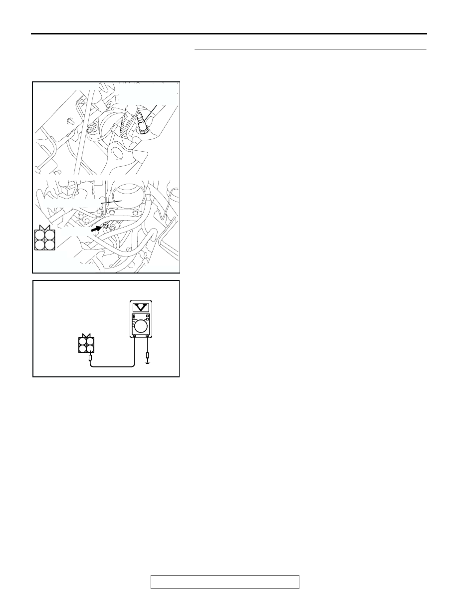
STEP 2. Measure the sensor output voltage at right bank 
heated oxygen sensor (front) connector B-09 by 
backprobing
(1) Do not disconnect the connector B-09.
(2) Start the engine and run at idle.

(3) Measure the voltage between terminal No. 4 and ground by 

backprobing.

• Warming up the engine. When the engine is 2,500 r/min, 

the output voltage should repeat 0 to 0.8 volt alternately.

(4) Turn the ignition switch to the "LOCK" (OFF) position.
Q: Is the measured voltage within the specified range?

YES : Go to Step 3.
NO :  Go to Step 7.

1

2

3

4

AK303048

B-09 (B)

CONNECTOR: B-09

THROTTLE BODY

RIGHT BANK
HEATED OXYGEN
SENSOR (FRONT)

AB

HARNESS
CONNECTOR:
COMPONENT SIDE

AK303049 AB

3

1 2

4

B-09 HARNESS 
CONNECTOR: 
HARNESS SIDE

MULTIPORT FUEL INJECTION (MFI) DIAGNOSIS

TSB Revision

MULTIPORT FUEL INJECTION (MFI) <3.8L ENGINE>

13B-194

STEP 3. Measure the sensor output voltage at PCM 
connector B-22 by using power plant ECU check harness 
special tool MB991923.
(1) Disconnect the all PCM connectors and connect power 

plant ECU check harness special tool MB991923 between 
the separated connectors.

(2) Start the engine and run at idle.

AK303016

104

96

94

95

93 92 91

99 98 97

103 102 101 100

108 107 106 105

113 112 111 110 109

CONNECTOR: B-22

B-22 (B)

PCM

AB

HARNESS CONNECTOR: 
COMPONENT SIDE

AIR CLEANER

AK202956

104

96

94

95

93 92 91

99 98 97

103 102 101 100

108 107 106 105

113 112 111 110 109

AB

POWER PLANT ECU 
CHECK HARNESS CONNECTOR

MB991923

PCM

MULTIPORT FUEL INJECTION (MFI) DIAGNOSIS

TSB Revision

MULTIPORT FUEL INJECTION (MFI) <3.8L ENGINE>

13B-195

(3) Measure the voltage between terminal No. 92 and ground.

• Warming up the engine. When the engine is 2,500 r/min, 

the output voltage should repeat 0 to 0.8 volt alternately.

(4) Turn the ignition switch to the "LOCK" (OFF) position.
Q: Is the measured voltage within the specified range?

YES : Go to Step 4.
NO :  Go to Step 6.

104

96

94

95

93 92 91

99 98 97

103 102 101 100

108 107 106 105

113 112 111 110 109

AK203091AB

POWER PLANT ECU 
CHECK HARNESS 
CONNECTOR 

MULTIPORT FUEL INJECTION (MFI) DIAGNOSIS

TSB Revision

MULTIPORT FUEL INJECTION (MFI) <3.8L ENGINE>

13B-196

STEP 4. Check harness connector B-09 at right bank 
heated oxygen sensor (front) and harness connector B-22 
at PCM for damage.
Q: Is the harness connector in good condition?

YES : Go to Step 5.
NO :  Repair or replace it. Refer to GROUP 00E, Harness 

Connector Inspection 

P.00E-2

. Then go to Step 15. 

1

2

3

4

AK303048

B-09 (B)

CONNECTOR: B-09

THROTTLE BODY

RIGHT BANK
HEATED OXYGEN
SENSOR (FRONT)

AB

HARNESS
CONNECTOR:
COMPONENT SIDE

AK303016

104

96

94

95

93 92 91

99 98 97

103 102 101 100

108 107 106 105

113 112 111 110 109

CONNECTOR: B-22

B-22 (B)

PCM

AB

HARNESS CONNECTOR: 
COMPONENT SIDE

AIR CLEANER


Content   ..  1123  1124  1125  1126   ..