Mitsubishi Galant (2004+). Manual - part 1074


  Index      Mitsubishi     Mitsubishi Galant - service repair manual 2004 year


Search            


Content   ..  1072  1073  1074  1075   ..


Mitsubishi Galant (2004+). Manual - part 1074


ON-VEHICLE SERVICE

TSB Revision

MULTIPORT FUEL INJECTION (MFI) <2.4L ENGINE>

13A-1113

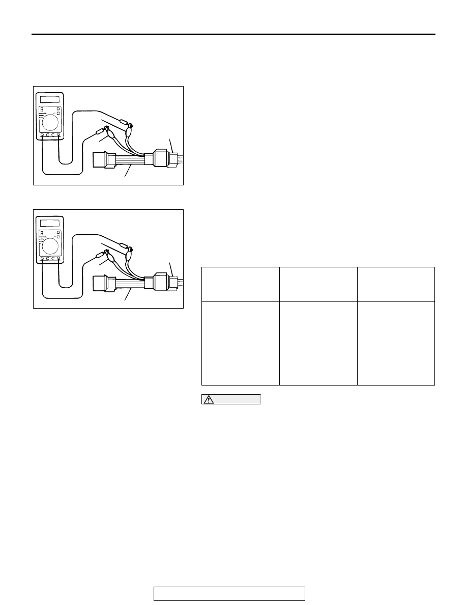
<Heated oxygen sensor (front)>
1. Using the scan tool MB991958, observe HO

2

S reading. If 

values are unsatisfactory, or if Scan tool is not available, use 
the following procedure:

(1) Disconnect the heated oxygen sensor connector and 

connect special tool MB991316 to the connector on the 
heated oxygen sensor side.

(2) Make sure that there is continuity [4.5 

− 8.0 ohms at 20°C 

(68

°F)] between terminal No. 1 (red clip) and terminal No. 

3 (blue clip) on the heated oxygen sensor connector.

(3) If there is no continuity, replace the heated oxygen 

sensor.

(4) Warm up the engine until engine coolant is 80

°C (176°F) 

or higher.

(5) Perform a revving for 5 minutes or more with the engine 

speed of 4,500 r/min.

(6) Connect a digital voltage meter between terminal No. 2 

(black clip) and terminal No. 4 (white clip).

2. While repeatedly revving the engine, measure the heated 

oxygen sensor output voltage.

Standard value:

CAUTION

• Be very careful when connecting the jumper wire; 

incorrect connection can damage the heated oxygen 
sensor.

• Be careful the heater is broken when voltage of beyond 

8 volts is applied to the heated oxygen sensor heater.

NOTE: If the sufficiently high temperature [of approximate 
400

°

C (752

°

F) or more] is not reached although the heated 

oxygen sensor is normal, the output voltage would be possi-
bly low although the rich air/fuel ratio. Therefore, if the out-
put voltage is low, use jumper wires to connect the terminal 
No. 1 (red clip) and the terminal No. 3 (blue clip) of the 
heated oxygen sensor with a (+) terminal and (-) terminal of 
8 volts power supply respectively, then check again.

3. If the output voltage is not within the standard value, replace 

the heated oxygen sensor.

ENGINE

HEATED OXYGEN 
SENSOR OUTPUT 
VOLTAGE

REMARKS

When revving 
engine

0.6 

− 1.0 volt

If you make the 
air/fuel ratio rich by 
revving the engine 
repeatedly, a 
normal heated 
oxygen sensor will 
output a voltage of 
0.6 

− 1.0 volt.

AKX01624 AB

MB991316

HEATED
OXYGEN
SENSOR
EQUIPMENT
SIDE
CONNECTOR

BLUE

RED

AKX01624

HEATED
OXYGEN
SENSOR
COMPONENT
SIDE
CONNECTOR

MB991316

WHITE

BLACK

AN

ON-VEHICLE SERVICE

TSB Revision

MULTIPORT FUEL INJECTION (MFI) <2.4L ENGINE>

13A-1114

NOTE: For removal and installation of the heated oxygen sen-
sor, refer to GROUP 15, Exhaust Pipe and Main Muffler 

P.15-21

.

ON-VEHICLE SERVICE

TSB Revision

MULTIPORT FUEL INJECTION (MFI) <2.4L ENGINE>

13A-1115

INJECTOR CHECK

M1131005200554

Measurement of Resistance between Terminals

1. Disconnect the injector connector.
2. Measure resistance between terminals.

Standard value: 10.5 

 13.5 ohms [at 20°C (68°F)]

3. If not within specification, replace the injector.
4. Install the injector connector.

Checking operation sound

Using a stethoscope or long blade screwdriver, check the oper-
ation sound ("tick-tick-tick") of injectors during idling or during 
cranking. Check that as the engine speed increases, the fre-
quency of the operating sound also increases.
1. If the injector you are checking is not operating, you may 

hear the operating sound of the other injectors.

2. If no operating sound is heard from the injector that is being 

checked, check the injector drive circuit. If there is nothing 
wrong with the circuit, a defective injector or powertrain 
control module (PCM) is suspected.

THROTTLE ACTUATOR CONTROL MOTOR 
CHECK

M1131051000100

.

<Operation Inspection>
1. Disconnect the air intake hose from the throttle body.
2. Set the ignition switch to the "ON" position.
3. Operate the accelerator pedal and confirm that the throttle 

valve is opening and closing accordingly.

.

<Checking the Terminal Resistance>
1. Disconnect the throttle position sensor connector.
2. Measure the resistance between terminal No. 1 and No. 2.

Standard value: 0.3 

 80 ohms [at 20°C (68°F)]

3. If resistance is outside the standard value, replace the 

throttle body assembly.

AK000602AB

1 2

AK000124 AB

STETHOSCOPE

6

1 2 3 4 5

AK202992

THROTTLE ACTUATOR
CONTROL MOTOR 
CONNECTOR

AB

ON-VEHICLE SERVICE

TSB Revision

MULTIPORT FUEL INJECTION (MFI) <2.4L ENGINE>

13A-1116

ENGINE OIL CONTROL VALVE CHECK

M1131053200070

.

Checking the Operation Sound
1. Disconnect the engine oil control valve connector.

CAUTION

To prevent the coil from burning, keep the duration of the 
voltage application as short as possible.
2. Check that the operation sound of the engine oil control 

valve can be heard when the positive battery voltage is 
supplied to the engine oil control valve. (Use the jumper 
wires to connect terminal No. 2 of the engine oil control 
valve connector to the positive battery terminal and terminal 
No. 1 to the negative battery terminal.)

3. If the operation sound cannot be heard, replace the engine 

oil control valve.

.

Checking the Coil Resistance
1. Disconnect the engine oil control valve connector.
2. Measure resistance between terminal No. 1 and terminal 

No. 2 of the connector at the engine oil control valve side.

Standard value: 6.9 

 7.9 ohms [at 20°C (68°F)]

3. If resistance is not within the standard value, replace the 

engine oil control valve.

EVAPORATIVE EMISSION PURGE SOLENOID 
CHECK

M1131005600273

Refer to GROUP 17, Emission Control System 

− Evaporative 

Emission Control System 

− Evaporative Emission Purge Sole-

noid Check 

P.17-89

.

EVAPORATVE EMISSION VENTILATION 
SOLENOID CHECK

M1131012800257

Refer to GROUP 17, Emission Control System 

− Evaporative 

Emission Canister and Fuel Tank Pressure Relief Valve 

− 

Evaporative Emission Canister and Fuel Tank Pressure Relief 
Valve Inspection 

P.17-98

.

EGR VALVE CHECK

M1131051500053

Refer to GROUP 17, Emission Control System 

− Exhaust Gas 

Recirculation (EGR) System 

− EGR Valve Check.

P.17-92

AK302171AB

ENGINE OIL 
CONTROL 
VALVE

MB991658

AK302152

1 2

AB

HARNESS CONNECTOR:
COMPONENT SIDE


Content   ..  1072  1073  1074  1075   ..