Mitsubishi Galant (2004+). Manual - part 1065


  Index      Mitsubishi     Mitsubishi Galant - service repair manual 2004 year


Search            


Content   ..  1063  1064  1065  1066   ..


Mitsubishi Galant (2004+). Manual - part 1065


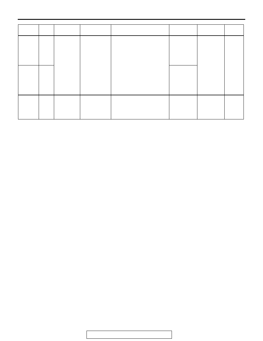
ACTUATOR TEST REFERENCE TABLE

TSB Revision

MULTIPORT FUEL INJECTION (MFI) <2.4L ENGINE>

13A-1077

RADIAT. 
FAN HI

20

Radiator 
fan, A/C 
condenser 
fan

Drive the fan 
motor

Ignition switch: "ON"

Radiator fan 
and 
condenser 
fan rotate at 
high speed.

Procedure 
No. 27

P.13A-
1018

RADIAT. 
FAN LO

21

Radiator fan 
and 
condenser 
fan rotate at 
low speed.

TCA 
FAIL 
SAFE

34

Throttle 
actuator 
control 
system

Stop the 
throttle 
actuator 
control motor

Ignition switch: "ON"

Throttle 
valve is 
opened 
slightly

Code No. 
P0638

P.13A-
782

MUT-III SCAN 
TOOL 
DISPLAY

ITEM NO.

INSPECTION ITEM

DRIVE CONTENTS

INSPECTION REQUIREMENT

NORMAL 
CONDITION

INSPECTION 
PROCEDURE NO.

REFERENCE 
PAGE

CHECK AT THE POWERTRAIN CONTROL MODULE (PCM)

TSB Revision

MULTIPORT FUEL INJECTION (MFI) <2.4L ENGINE>

13A-1078

CHECK AT THE POWERTRAIN CONTROL MODULE (PCM)

M1131153600332

1. Disconnect the PCM connectors B-19, B-20, 

B-21, B-22 and B-23, and connect check harness 
special tool MB991923 between the PCM 
connectors.

2. Measure the voltage between each check 

harness connector terminal and check harness 
connector ground terminal (No. 25 or No. 29).

TERMINAL VOLTAGE CHECK CHART
NOTE: *

1

: The average voltage through an analog voltmeter is described in this service manual (because the 

average voltage is too stable to be shown on a digital voltmeter).
NOTE: *

2

: Vehicles for Canada, the headlight, taillight, etc. remain lit even when the lighting switch is in "OFF" 

position but this is no problem for checks.

AK203309

4 3 2 1

7 6 5

9 8

11 10

14 13 12

18 17 16 15

25

21

24 23 22

29 28 27 26

34 33 32 31 30

38 37 36 35

43 42 41 40 39

55

56

54 53 52 51

57

62 61 60 59 58

63

69 68 67 66 65 64

70

75 74 73 72 71

76

82 81 80 79 78 77

83

104

96

94

95

93 92 91

99 98 97

103 102 101 100

108 107 106 105

113 112 111 110 109

127 126 125 124 123 122 121

133 132 131 130 129 128

140 139 138 137 136 135 134

146 145 144 143 142 141

153 152 151 150 149 148 147

AB

Check Harness Special Tool MB991923 Connector Terminal Arrangement

TERMINAL NO. INSPECTION 

ITEM

INSPECTION CONDITION (ENGINE 
CONDITION)

NORMAL 
CONDITION

2

Evaporative 
emission 
ventilation solenoid

Ignition switch: "ON"

B+

Carry out the actuator test to drive the solenoid 
valve.

For 
approximately 6 
seconds 1 V or 
less

5

Fan control relay 
(high)

Ignition switch: "ON"

B+

Carry out the actuator test to revolve the fan at 
low speed.

1 V or less

6

Fuel pump relay

Ignition switch: "ON"

B+

Engine: idling

1 V or less

10

Fan control relay 
(low)

Ignition switch: "ON"

B+

Carry out the actuator test to revolve the fan at 
low speed.

1 V or less

21

Sensor supplied 
voltage

Ignition switch: "ON"

4.9 

− 5.1 V

68
23

Fuel tank 
differential 
pressure sensor

Engine: idling

1.2 

− 3.8 V

26

Accelerator pedal 
position sensor 
(main)

Ignition switch: 
"ON"

Release the accelerator 
pedal

0.7 

− 1.3 V

Depress the accelerator 
pedal fully

4.0 V or more

27

Accelerator pedal 
position sensor 
(sub)

Ignition switch: 
"ON"

Release the accelerator 
pedal

0.4 

− 1.0 V

Depress the accelerator 
pedal fully

3.7 V or more

CHECK AT THE POWERTRAIN CONTROL MODULE (PCM)

TSB Revision

MULTIPORT FUEL INJECTION (MFI) <2.4L ENGINE>

13A-1079

30

Power supply 
voltage applied to 
accelerator pedal 
position sensor 
(main)

Ignition switch: "ON"

4.9 

− 5.1 V

41

Fuel tank 
temperature 
sensor

Ignition switch: 
"ON"

When fuel tank temperature 
is 0

°C (32°F)

2.7 

− 3.1 V

When fuel tank temperature 
is 20

°C (68°F)

2.1 

− 2.5 V

When fuel tank temperature 
is 40

°C (104°F)

1.6 

− 2.0 V

When fuel tank temperature 
is 80

°C (176°F)

0.8 

− 1.2 V

42

Backup power 
supply

Ignition switch: "LOCK" (OFF)

B+

43

Ignition switch-IG

Ignition switch: "ON" 

B+

51

Power supply

Ignition switch: "ON"

B+

64
52

MFI relay (power 
supply)

Ignition switch: "LOCK" (OFF)

B+

Ignition switch: "ON"

1 V or less

78

Power steering 
pressure switch

Engine: warming 
up, idling

When steering wheel is not 
turned

B+

When steering wheel is 
turned

1V or less

81

A/C compressor 
clutch relay

• Engine: idling

• A/C switch: OFF→ ON (A/C compressor is 

operating)

B+

→ 1 V or less 

as A/C clutch 
cycles

83

Ignition switch-ST

Engine: cranking

8 V or more

91

Cylinder 2, 3 
heated oxygen 
sensor (front)

Engine: warming up, 2,500 r/min

⇔ 0.8 V 

(changes 
repeatedly) 

92

Cylinder 1, 4 
heated oxygen 
sensor (front)

Engine: warming up, 2,500 r/min

⇔ 0.8 V 

(changes 
repeatedly) 

TERMINAL NO. INSPECTION 

ITEM

INSPECTION CONDITION (ENGINE 
CONDITION)

NORMAL 
CONDITION

CHECK AT THE POWERTRAIN CONTROL MODULE (PCM)

TSB Revision

MULTIPORT FUEL INJECTION (MFI) <2.4L ENGINE>

13A-1080

93

Engine coolant 
temperature 
sensor

Ignition switch: 
"ON"

When engine coolant 
temperature is 

−20°C (−4°F)

3.9 

− 4.5 V

When engine coolant 
temperature is 0

°C (32°F)

3.2 

− 3.8 V

When engine coolant 
temperature is 20

°C (68°F)

2.3 

− 2.9 V

When engine coolant 
temperature is 40

°C (104°F)

1.3 

− 1.9 V

When engine coolant 
temperature is 60

°C (140°F)

0.7 

− 1.3 V

When engine coolant 
temperature is 80

°C (176°F)

0.3 

− 0.9 V

94

Power supply 
voltage applied to 
throttle position 
sensor

Ignition switch: "ON"

4.9 

− 5.1 V

96

Cylinder 2, 3 
heated oxygen 
sensor (rear)

• Engine: warming up

• Revving

0 and 0.6 

− 1.0 V 

alternates

97

Cylinder 1, 4 
heated oxygen 
sensor (rear)

• Engine: warming up

• Revving

0 and 0.6 

− 1.0 V 

alternates

98

Throttle position 
sensor (sub)

• Remove the 

intake air hose 
at the throttle 
body

• Disconnect the 

throttle position 
sensor 
connector, and 
then connect 
terminal 
numbers No. 3, 
No. 4, No. 5 and 
No. 6 with the 
use of the 
special tool: 
MB991658.

• Ignition switch: 

"ON"

Fully close the throttle valve 
with your finger

2.2 

− 2.8 V

Fully open the throttle valve 
with your finger

4.0 V or more

TERMINAL NO. INSPECTION 

ITEM

INSPECTION CONDITION (ENGINE 
CONDITION)

NORMAL 
CONDITION


Content   ..  1063  1064  1065  1066   ..