Mitsubishi Galant (2004+). Manual - part 1044


  Index      Mitsubishi     Mitsubishi Galant - service repair manual 2004 year


Search            


Content   ..  1042  1043  1044  1045   ..


Mitsubishi Galant (2004+). Manual - part 1044


MULTIPORT FUEL INJECTION (MFI) DIAGNOSIS

TSB Revision

MULTIPORT FUEL INJECTION (MFI) <2.4L ENGINE>

13A-993

STEP 3. Check the ignition timing.
Refer to GROUP 11A, On-vehicle Service 

− Ignition Timing 

Check 

P.11A-12

.

Q: Is the ignition timing normal?

YES : Go to Step 4.
NO :  Check that the crankshaft position sensor and timing 

belt cover are in the correct position. Then confirm 
that the malfunction symptom is eliminated.

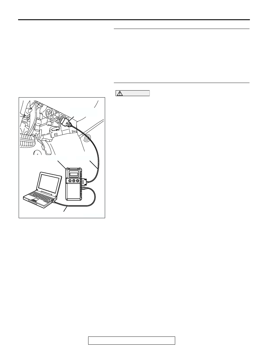
STEP 4. Using scan tool MB991958, check data list.

CAUTION

To prevent damage to scan tool MB991958, always turn the 
ignition switch to the "LOCK" (OFF) position before con-
necting or disconnecting scan tool MB991958.
(1) Connect scan tool MB991958 to the data link connector.
(2) Turn the ignition switch to the "ON" position.
(3) Check the following items in the data list. Refer to Data List 

Reference Table 

P.13A-1063

.

a. Item 13: Intake Air Temperature Sensor.
b. Item 25: Barometric Pressure Sensor.

c. Item 21: Engine Coolant Temperature Sensor.

d. Item 69: Cylinder 1, 4 Heated Oxygen Sensor (rear).
e. Item 39: Cylinder 1, 4 Heated Oxygen Sensor (front).

f. Item 59: Cylinder 2, 3 Heated Oxygen Sensor (rear).

g. Item 11: Cylinder 2, 3 Heated Oxygen Sensor (front).

(4) Turn the ignition switch to the "LOCK" (OFF) position.
Q: Are they operating properly?

YES : Go to Step 5.
NO :  Repair or replace it. Then confirm that the malfunction 

symptom is eliminated.

AK303804AB

MB991910

DATA LINK
CONNECTOR

MB991824

MB991827

MULTIPORT FUEL INJECTION (MFI) DIAGNOSIS

TSB Revision

MULTIPORT FUEL INJECTION (MFI) <2.4L ENGINE>

13A-994

STEP 5. Using scan tool MB991958, check data list.
(1) Turn the ignition switch to the "ON" position.
(2) Check the following items of data list. Refer to Data List 

Reference Table 

P.13A-1063

.

a. Item 39: Cylinder 1, 4 Heated Oxygen Sensor (front).
b. Item 11: Cylinder 2, 3 Heated Oxygen Sensor (front).

• Voltage should fluctuate between 0 − 0.4 volt and 0.6 − 

1.0 volt while idling after the engine has been warmed.

(3) Turn the ignition switch to the "LOCK" (OFF) position.
Q: Are they operating properly?

YES : Go to Step 7.
NO :  Go to Step 6.

STEP 6. Check the fuel pressure.
Refer to On-vehicle Service 

− Fuel Pressure Test 

P.13A-1104

.

Q: Is the fuel pressure normal?

YES : Check the following items, and repair or replace the 

defective items.

a. Vacuum leak.

• Broken intake manifold gasket.

• Broken air intake hose.

• Broken vacuum hose.

• Positive crankcase ventilation valve does 

not operate.

b. Injector clogged.

Then confirm that the malfunction symptom is 

eliminated.

NO :  Repair or replace it. Then confirm that the malfunction 

symptom is eliminated.

AK303804AB

MB991910

DATA LINK
CONNECTOR

MB991824

MB991827

MULTIPORT FUEL INJECTION (MFI) DIAGNOSIS

TSB Revision

MULTIPORT FUEL INJECTION (MFI) <2.4L ENGINE>

13A-995

STEP 7. Check the fuel pressure.
Refer to On-vehicle Service 

− Fuel Pressure Test 

P.13A-1104

.

Q: Is the fuel pressure normal?

YES : Check the following items, and repair or replace the 

defective items.

a. Check the ignition coil and spark plugs.
b. Check compression pressure.

c. Check the fuel filter or fuel line for clogging.

d. Check the EGR system.
e. Broken air intake hose.

f. Clogged air cleaner.

g. Clogged exhaust system.

Then confirm that the malfunction symptom is 

eliminated.

NO :  Repair or replace it. Then confirm that the malfunction 

symptom is eliminated.

MULTIPORT FUEL INJECTION (MFI) DIAGNOSIS

TSB Revision

MULTIPORT FUEL INJECTION (MFI) <2.4L ENGINE>

13A-996

INSPECTION PROCEDURE 19: Surge.

.

COMMENT

• Defective ignition system, abnormal air/fuel ratio, 

the electronic control throttle valve system failed, 
etc. are suspected.

.

TROUBLESHOOTING HINTS (The most likely 
causes for this case:)

• Malfunction of the ignition system.

• Malfunction of air/fuel ratio control system.

• Malfunction of the electronic control throttle valve 

system.

• Malfunction of the EGR system.

DIAGNOSIS

Required Special Tools:

• MB991958: Scan Tool (MUT-III Sub Assembly)

• MB991824: V.C.I.

• MB991827: USB Cable

• MB991910: Main Harness A

STEP 1. Using scan tool MB991958, read the diagnostic 
trouble code (DTC).

CAUTION

To prevent damage to scan tool MB991958, always turn the 
ignition switch to the "LOCK" (OFF) position before con-
necting or disconnecting scan tool MB991958.
(1) Connect scan tool MB991958 to the data link connector.
(2) Turn the ignition switch to the "ON" position.
(3) Read the DTC.
(4) Turn the ignition switch to the "ON" position.
Q: Is the DTC set?

YES : Refer to Diagnostic Trouble Code Chart 

P.13A-34

.

NO :  Go to Step 2.

AK303804AB

MB991910

DATA LINK
CONNECTOR

MB991824

MB991827


Content   ..  1042  1043  1044  1045   ..