Mitsubishi Galant (2004+). Manual - part 33


  Index      Mitsubishi     Mitsubishi Galant - service repair manual 2004 year


Search            


Content   ..  31  32  33  34   ..


Mitsubishi Galant (2004+). Manual - part 33


WELDING

TSB Revision

BASE OF BODY REPAIR

9-11

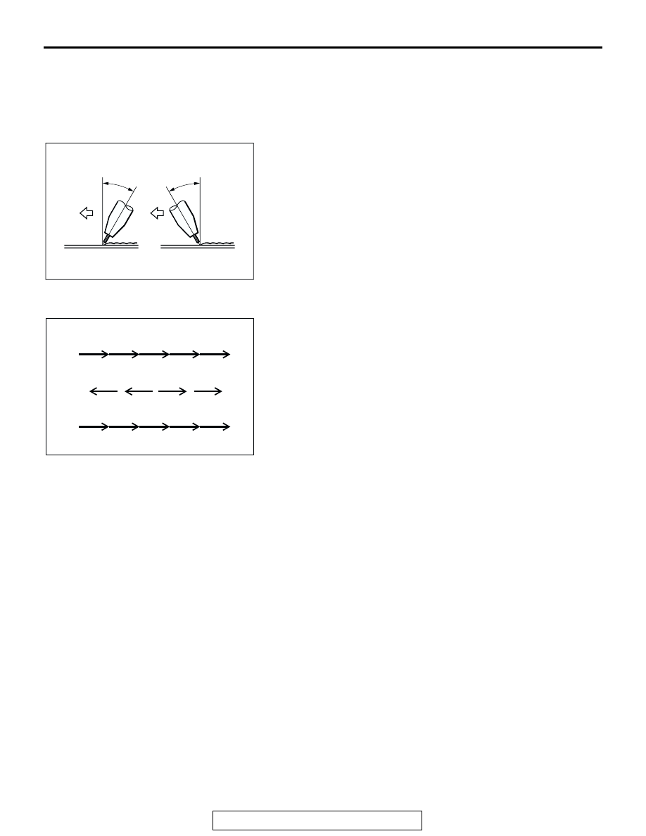
Torch angle and welding technique
There are two welding techniques: forehand welding and back-
hand welding.
Forehand welding: Penetration is shallow and the bead is flat.
Backhand welding: Penetration is deep and the bead has a 

convex shape.

The angle of the torch should be 15 

 30 degree angle for 

either technique, and the tip should be maintained at a distance 
of 6 

 10 mm (0.2 

 0.4 inch) from the surface being welded.

.

Preventing warping

1. Backhand technique

Because the direction for each weld pass and that for the 
fusion progression are opposite, the residual stress is 
evenly distributed.

2. Symmetrical technique

Because the welds are made in symmetrical positions in 
relation to the center of the joint, the residual stress is also 
symmetrical.

3. "Stepping stone" technique

Because the welds are made at random positions, the 
residual stress is the most evenly distributed; however, the 
possibility of flaws at the starting and stopping points is rela-
tively high.

NOTES REGARDING MIG WELDING

Note the following notes regarding MIG welding.

1. The surface to be welded must be perfectly 

clean; be sure to remove any non-conductive 
paint.

2. If the end of the wire forms into a ball, it will 

adversely affect the formation of the arc; cut the 
end off with a pair of wire snips or a similar tool.

3. Select a welding current to match the thickness of 

the panels being welded.

4. For continuous welding, maintain a constant weld 

speed and keep both the height and the width of 
the bead constant.
In addition, the tack welding pitch and the welding 
bead should be shorter as the thickness of the 
panels being welded decreases.

AB301457

15 – 30˚

15 – 30˚

FOREHAND
TECHNIQUE

BACKHAND
TECHNIQUE

AB

AB200043 AB

ANTI-WARP WELDING TECHNIQUES

1.

2.

3.

BACKHAND TECHNIQUE

SYMMETRICAL TECHNIQUE

"STEPPING STONE" TECHNIQUE

5

4

3

2

1

5

4

3

2

1

4

3

2

1

WELDING

TSB Revision

BASE OF BODY REPAIR

9-12

OTHER TYPES OF WELDING

M4090004000024

BRAZING

In brazing, a filler metal is melted into the joint of the 
panels to be welded at a comparatively low tempera-
ture to fuse them together without melting the panels 
themselves. In other words, through the aid of a flux 
and because of the capillarity phenomenon, the mol-
ten filler metal will flow into the joint between the two 
panels which are in contact with each other and 
spread along the metal surfaces. When this molten 
filler metal cools and solidifies, it will from a strong 
joint of the two panels. Note that, if two panels of dif-
ferent kinds of metal are brazed, the electrolysis gen-
erated between the two metals will cause moisture to 
from, which will result in corrosion.
Panels should not be connected together by brazing 
at any place except those places indicated. The fol-
lowing materials (filler metals) are usually used for 
brazing.

1. Brass filler metal (brass solder)

Brass filler metal is an alloy consisting of 60% 
copper and 40% zinc with a melting temperature 
of approximately 850 

 1,050

°

C (1,562 


1,922

°

F), and it is the most commonly used braz-

ing filler metal used for body repair.
The filler metal itself is coated with flux to facili-
tate penetration between the panels to be joined.

2. Silver alloy filler metal (silver solder)

Silver alloy filler metal consists of silver, copper, 
zinc or cadmium, nickel, and tin, or other metals.
This filler metal is most applicable for the brazing 
of steel and non-ferrous alloy other than alumin-
ium, magnesium, and others with low melting 
points.

Notes with regard to brazing work

Use a wire brush, sandpaper, file etc., to remove 
any oxide film grease, dirt, etc., from the surfaces 
of the panels to be brazed.

When doing brass brazing, if the panels and the 
filler metal are heated excessively, a weak 
iron-copper alloy will form, which could crack 
easily. Be careful not to apply excessive heat.

The joint of the panels must overlap as indicated 
in the illustration.

AB200044

EXAMPLES OF BRAZED JOINTS

AC

WELDING

TSB Revision

BASE OF BODY REPAIR

9-13

GAS WELDING

Gas welding is a method in which a high temperature flame is 
used to melt both a welding rod and the base metal (panels) to 
make a fused joint. Oxy-acetylene is the most common type of 
gas welding. However, because of the extremely high tempera-
ture of the fused joint, the strength of the steel plate deterio-
rates, and there is a higher possibility of warping. This method, 
therefore, is not very suitable for body repair.

.

The flame in gas welding can be classified according 
to the ratio of acetylene and oxygen.

1. Carburizing flame (acetylene-rich flame)

This flame has an excess of acetylene or a defi-
ciency of oxygen. The incomplete combustion 
gives off a black smoke, and two flame cores can 
be seen inside the deformed yellow flame. The 
flame itself is large, but the temperature is rela-
tively low, making this flame unsuitable for weld-
ing.

2. Standard flame (neutral-mixture flame)

This flame has approximately equal amounts of 
acetylene and oxygen. The length is shorter than 
that of the carburizing flame; the flame core is 
rounded; and it is clear and bright.
The carbon in the acetylene is burned completely, 
resulting in the maximum obtainable temperature.
This is the flame most commonly used for weld-
ing.

3. Peroxide flame (oxygen-rich flame)

This flame has an excess of oxygen or a defi-
ciency of acetylene. The flame core is shorter 
and sharper, and the entire flame has a black-
ish-purplish color. The combustion is unstable, 
and the flame flickers continuously.

.

Notes with regard to gas welding

1. Handle the oxygen and acetylene tanks carefully.
2. Adjust the flame in accordance with the type of 

metal being welded.

3. Select a nozzle to match the work to be done. 

Avoid overheating and adhesion of foreign matter 
(dirt, etc.)

4. The following points are particularly important 

when welding mild steel plate.

Melt a sufficient amount of welding rod, but be 
careful not to melt the base metal. Use the 
same amount of welding rod on both sides.

Use the correct amount of welding rod in 
accordance with the melting point of the base 
metal.

Avoid welding over places which have been 
welded before.

In order to avoid warping, do only the amount 
of tack welding that is absolutely required.

AB200049

DEPOSITE

BASE METAL

WELDING 
ROD

OXY-ACETYLENE
FLAME

AB

AB200050

FLAME CORE

OUTER FLAME

ACETYLENE CONE

AC

1. CARBURIZING FLAME

OUTER FLAME

OUTER FLAME

FLAME CORE

FLAME CORE

2. STANDARD FLAME

3. PEROXIDE FLAME

BODY REPAIR

TSB Revision

BASE OF BODY REPAIR

9-14

BODY REPAIR

STANDARD BODY REPAIR PROCEDURES

M4090006000042

The following is an explanation of the standard repair 
procedures for the monocoque body and the 
frame-type body. Furthermore, please refer to the 
replacement of welded panels for the applicable 
model for information concerning the procedures for 
replacement of panels (as classified by position) for 
the various models.
NOTE: That reference should be made to page 

P.9-27

 concerning repair procedures for the frame of 

frame-type vehicles.

STANDARD PROCEDURES FOR 
REPLACEMENT OF WELDED PANELS

In order to maintain the proper levels of strength, 
rigidity, and precision when making welded panel 
replacements, it is essential to first gain a thorough 
understanding of the body structure, and then to per-
form all repair operations carefully and correctly. In 
addition, when performing the operations, be sure to 
use the proper protective equipment for each opera-
tion.

.

CAUTION

Select an appropriate location for the cutting operation, 
and perform the work carefully, so as not to cut into the 
reinforcements located inside the pillars, panels which 
are not be replaced, or any other such parts.

There are harnesses, hoses, and other such parts 
routed inside the front pillar, the rear pillar, the fender 
shield, the side sill, etc.; perform the repair work only 
after any such material has been removed.

For overlap cutting, allow an overlap of approximately 
30 

 50 mm (1.2 

 2.0 inches) when performing the cut-

ting operation.

1. Rough cutting of panels

First make a rough cutting of a portion of the panel to be 
replaced, and then remove that portion, thus making it 
easier to break the spot welds.

2. Removal of the paint coat from spot-welded points

In order to clearly identify the spot-welded points, remove 
the paint coat from areas where it is difficult to determine the 
spot welds.

3. Cutting and separation of spot-welded points

In order to perform cutting and separation of spot-welded 
points, use a spot weld cutter which is larger than the size of 
the nugget to make a hole only in the panels to be replaced.
When cutting and separating spot-welded points in places 
where the surrounding panel or other parts interfere with the 
spot weld cutter, or if the operation is hampered by a lack of 
space, bend back the flanges in order to make the work 
easier.
If a spot-weld cutter cannot be used at all, cut and separate 
the spot welds by using a chisel or similar tool.

AB200051

AB200052

AB200053


Content   ..  31  32  33  34   ..