Mitsubishi Galant. Manual - part 728


  Index      Mitsubishi     Mitsubishi Galant - service repair manual 2001 year


Search            


Content   ..  726  727  728  729   ..


Mitsubishi Galant. Manual - part 728


COMPRESSOR ASSEMBLY AND TENSION PULLEY

TSB Revision

HEATING AND AIR CONDITIONING

55-38

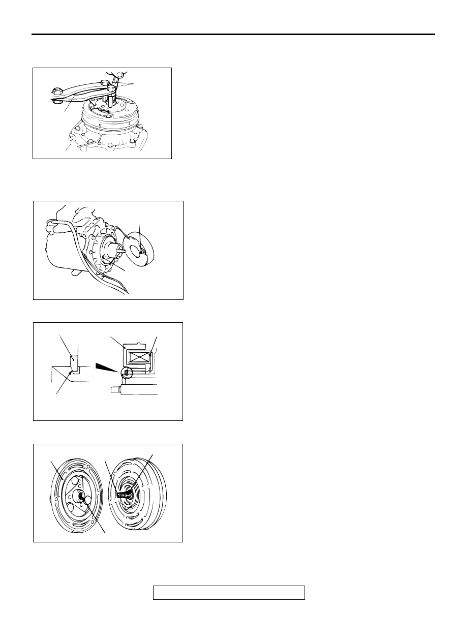
DISASSEMBLY SERVICE POINT

<<A>> NUT REMOVAL
Use special tools MB991367 and MB991386 to hold the 
magnetic clutch, and remove the nut.

ASSEMBLY SERVICE POINTS

>>A<< CLUTCH COIL INSTALLATION
When installing the clutch coil to the A/C compressor body, 
install so that the pin hole of the A/C compressor body and the 
clutch coil projection are aligned.

>>B<< SNAP RING INSTALLATION
Install the snap ring so that the tapered surface is to the 
outside.

>>C<< ARMATURE PLATE INSTALLATION
Align the serration protrusion on the crankshaft with the notch 
on the armature and install.

AC001410

MB991386

MB991367

AB

AC001411AB

CLUTCH COIL
PROJECTION

COMPRESSOR
BODY PIN HOLE

AC001412

SNAP RING

ROTOR

CLUTCH COIL

TAPERED PART

AB

AC001413AB

ARMATURE
PLATE

SERRATION
NOTCH

CRANK-
SHAFT

SERRATION PROTRUSION

COMPRESSOR ASSEMBLY AND TENSION PULLEY

TSB Revision

HEATING AND AIR CONDITIONING

55-39

>>D<< NUT INSTALLATION
Use special tools MB991367 and MB991386 to hold the 
magnetic clutch, and tighten the nut in the same manner as for 
removal.

>>E<< AIR GAP ADJUSTMENT
Check whether or not the air gap of the clutch is within the 
standard value.

Standard value:

••••

<2.4L engine> 0.3 

−−−−

 0.5 mm (0.012 

−−−−

 0.020 inch)

••••

<3.0L engine> 0.4 

−−−−

 0.6 mm (0.016 

−−−−

 0.024 inch)

NOTE: If there is a deviation of the air gap from the standard 
value, make the necessary adjustment by adjusting the number 
of shims.

AC001414

MB991386

MB991367

AB

AC001415

FEELER GAUGE

AB

CONDENSER AND CONDENSER FAN MOTOR

TSB Revision

HEATING AND AIR CONDITIONING

55-40

CO ND ENSER  A ND  C O N D ENSER  FA N  M O TO R

CONDENSER AND CONDENSER FAN MOTOR

M1552006700072

REMOVAL AND INSTALLATION

AC002948

1

3

4

5

7

2

AC

6

6

N

PIPING CONNECTION

COMPRESSOR OIL: SUN PAG 56

4.9 N·m
43.4 in-lb    

4.9 N·m
43.4 in-lb    

CONDENSER FAN MOTOR <3.0L 
ENGINE> REMOVAL STEPS

1.

CONDENSER FAN MOTOR AND 
SHROUD ASSEMBLY

2.

CONDENSER FAN

3.

SHROUD

4.

CONDENSER FAN MOTOR
CONDENSER REMOVAL STEPS

REFRIGERANT DISCHARGING 
AND CHARGING (REFER TO 

P.55-21

.)

AIR CLEANER (REFER TO 
GROUP 15, AIR CLEANER 

P.15-

4

.)

ENGINE COOLANT DRAINING 
AND SUPPLYING (REFER TO 
GROUP 14, ON-VEHICLE 
SERVICE 

P.14-14

.)

RADIATOR (REFER TO GROUP 
14, RADIATO

P.14-14

.)

<<A>>

5.

DISCHARGE HOSE AND LIQUID 
PIPE A

6.

O-RING

>>A<<

7.

CONDENSER

CONDENSER REMOVAL STEPS 

REFRIGERANT LINE

TSB Revision

HEATING AND AIR CONDITIONING

55-41

REMOVAL SERVICE POINT

<<A>> LIQUID PIPE A/DISCHARGE HOSE 
DISCONNECTION

CAUTION

Seal the hoses completely, otherwise the compressor oil 
and receiver will absorb water vapor easily, possibly 
damaging the compressor and deteriorating performance.
Plug the disconnected pipe, hose and condenser nipple to 
prevent foreign material from getting into them.

INSTALLATION SERVICE POINT

>>A<< CONDENSER INSTALLATION
When replacing the condenser, refill it with a specified amount 
of compressor oil and install it. (to the vehicle).

••••

Compressor oil: SUN PAG 56

••••

Quantity: 15 cm

3

 (0.5 floz)

INSPECTION

M1552006800079

CONDENSER FAN MOTOR CHECK

Check to be sure that the condenser fan motor operates when 
battery voltage is applied to terminal 2 and terminal 1 
grounded.

R EFR IG ER A N T LIN E

REFRIGERANT LINE

M1552006400082

REMOVAL AND INSTALLATION

Pre-removal and Post-installation Operation

Refrigerant Discharging and Charging (Refer to 

P.55-21

.)

AC001417AB


Content   ..  726  727  728  729   ..