Mitsubishi Galant. Manual - part 696


  Index      Mitsubishi     Mitsubishi Galant - service repair manual 2001 year


Search            


Content   ..  694  695  696  697   ..


Mitsubishi Galant. Manual - part 696


SWS DIAGNOSIS

TSB Revision

SIMPLIFIED WIRING SYSTEM (SWS)

54B-179

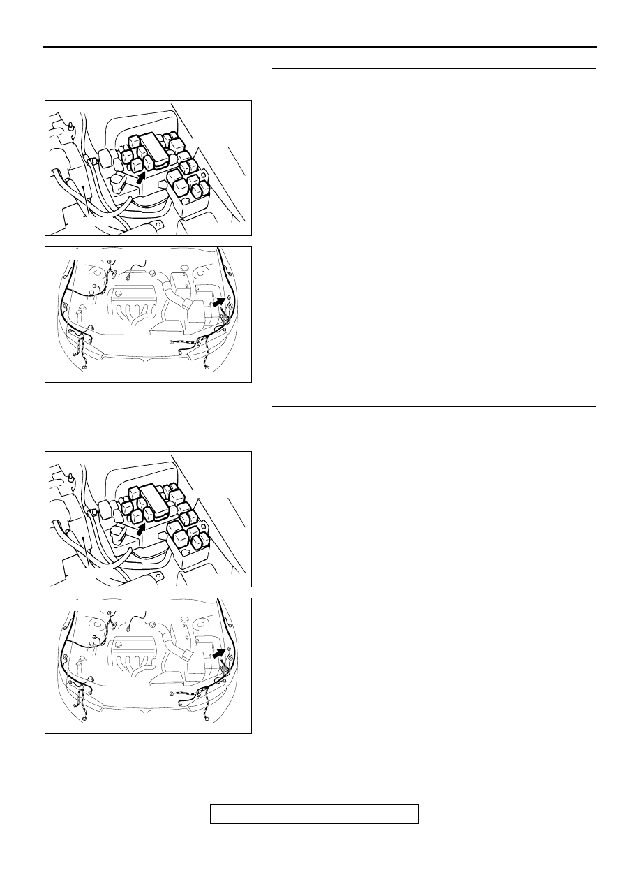
STEP 9. Check the theft-alarm horn relay connector A-11X 
and theft-alarm horn connector A-23 for damage.
Q: Are theft-alarm horn relay connector A-11X and theft-

alarm horn connector A-23 in good condition?
YES : 
Go to Step 10.
NO :  Repair or replace them. Refer to GROUP 00E, 

Harness Connector Inspection 

P.00E-2

  . The horn 

should sound when the theft-alarm system is 
triggered.

STEP 10. Check the harness wire between theft-alarm horn 
relay connector A-11X and theft-alarm horn connector A-
23.
Q: Is the harness wire between horn relay connector A-11X 

and theft-alarm horn connector A-23 in good condition?
YES : 
Go to Step 11.
NO :  Repair it. The horn should sound when the theft-alarm 

system is triggered.

AC003128 AM

CONNECTOR: A-11X

THEFT-
ALARM 
HORN
RELAY

BATTERY

AC003129 AF

CONNECTOR: A-23

AC003128 AM

CONNECTOR: A-11X

THEFT-
ALARM 
HORN
RELAY

BATTERY

AC003129 AF

CONNECTOR: A-23

SWS DIAGNOSIS

TSB Revision

SIMPLIFIED WIRING SYSTEM (SWS)

54B-180

STEP 11. Check that the theft-alarm horn is installed 
properly.

NOTE: The theft-alarm horn is grounded to the body through 
the installation bolts.

Q: Is the theft-alarm horn installation in good condition?

YES : Replace the ETACS-ECU. The horn should sound 

when the theft-alarm system is triggered.

NO :  Repair it. The horn should sound when the theft-alarm 

system is triggered.

Inspection Procedure M-3: Theft-alarm system: Headlights (high-beam) do not flash when the theft-
alarm system is triggered.

HEADLIGHTS (HIGH-BEAM) DO NOT FLASH 
WHEN THE THEFT-ALARM SYSTEM IS 
TRIGGERED
If the headlights (high-beam) work normally, the 
front-ECU or the ETACS-ECU may be defective.

TROUBLESHOOTING HINTS

Malfunction of the front-ECU 

Malfunction of the ETACS-ECU

Damaged harness wires or connectors

DIAGNOSIS

STEP 1. Check the headlight (high-beam) operation.

Q: Do the headlights (high-beam) illuminate normally?

YES : Go to Step 2.
NO :  Solve the problem first. Refer t

P.54B-128

.

STEP 2. Replacement of ECU
(1)Replace the ETACS-ECU.
(2)The headlights (high-beam) should flash when the theft-

alarm system is triggered.

Q: Do the headlights (high-beam) flash normally by the 

theft-alarm system?
YES : 
There is no action to be taken.
NO :  Replace the front-ECU. The headlights (high-beam) 

should flash when the theft-alarm system is triggered.

Inspection Procedure M-4: Theft-alarm system: Panic alarm fonction does not work.

PANIC ALARM FUNCTION DOES NOT WORK
If the keyless entry system is normal, the ETACS-
ECU is defective.

TROUBLESHOOTING HINTS

Malfunction of the ETACS-ECU 

Damaged harness wires or connectors 

DIAGNOSIS

Required Special Tools:

MB991502: Scan Tool (MUT-II)

MB991529: Diagnostic Trouble Code Check Harness

SWS DIAGNOSIS

TSB Revision

SIMPLIFIED WIRING SYSTEM (SWS)

54B-181

STEP 1. Check the keyless entry system.

Q: Does the keyless entry system work normally?

YES : Go to Step 2<when using scan tool MB991502> or 

3<when using a voltmeter>.

NO :  Solve the problem first. Refer t

P.54B-9

.

STEP 2. Check the input signal (by using scan tool 
MB991502).
Check the input signals from the transmitter "PANIC" switch.

CAUTION

To prevent damage to scan tool MB991502, always turn the 
ignition switch to the "LOCK" (OFF) position before 
connecting or disconnecting scan tool MB991502.
(1)Connect scan tool MB991502 to the data link connector.
(2)Check that the tone alarm of scan tool MB991502 sounds 

when the input signal enters.

Q: Does the tone alarm of scan tool MB991502 sound when 

the input signal enters?
YES : 
Replace the ETACS-ECU. The panic alarm should 

work normally.

NO :  Check the transmitter input signal circuit. Refer to 

Inspection Procedure N-17 (

P.54B-265

 ).

STEP 3. Check the input signal (by using a voltmeter).
Check the input signals from the transmitter "PANIC" switch.
(1)Use special tool MB991529 to connect a voltmeter between 

ground terminal 4 or 5 and ETACS-ECU terminal 9 of the 
data link connector.

(2)Check that the voltmeter indicator deflects once when the 

input signal enters.

Q: Does the voltmeter indicator deflect?

YES : Replace the ETACS-ECU. The panic alarm should 

work normally.

NO :  Check the transmitter input signal circuit. Refer to 

Inspection Procedure N-17 (

P.54B-265

 ).

AC003081 AB

16 PIN

MB991502

AC003083

16 PIN

AB

ETACS-ECU
TERMINAL

GROUNDED TERMINAL

MB991529

SWS DIAGNOSIS

TSB Revision

SIMPLIFIED WIRING SYSTEM (SWS)

54B-182

Inspection Procedure N-1: The ignition switch (ACC) signal is not sent to the ETACS-ECU.

CIRCUIT OPERATION.
The ETACS-ECU operates various functions 
according to the input signal from the ignition switch 
(ACC).

TECHNICAL DESCRIPTION (COMMENT)
The ignition switch (ACC) input signal is used to 
operate the windshield wiper and washer. If the 
signal fails, windshield wiper and washer will not 
work normally.

NOTE: The windshield wiper and washer works 
normally if a normal ignition switch (ACC) signal is 
sent from the ignition switch directly to the front-ECU.

TROUBLESHOOTING HINTS

Malfunction of the ETACS-ECU

Damaged harness wires or connectors

DIAGNOSIS

Required Special Tools:

MB991223: Test Harness Set

Ignition Switch (ACC) Input Circuit

AC004233

AC003082AD

JUNCTION BLOCK
(FRONT VIEW)

CONNECTOR: C-73

AC003080 AD

JUNCTION BLOCK
(REAR VIEW)

CONNECTOR: C-86


Content   ..  694  695  696  697   ..