Mitsubishi Galant. Manual - part 684


  Index      Mitsubishi     Mitsubishi Galant - service repair manual 2001 year


Search            


Content   ..  682  683  684  685   ..


Mitsubishi Galant. Manual - part 684


SWS DIAGNOSIS

TSB Revision

SIMPLIFIED WIRING SYSTEM (SWS)

54B-131

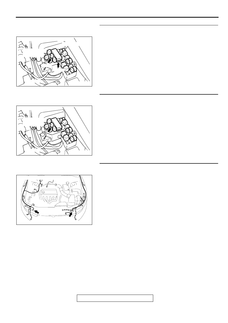
STEP 8. Check headlight relay (high) connector A-07X and 
front-ECU connector A-09X for damage.
Q: Are headlight relay (high) connector A-07X and front-

ECU connector A-09X in good condition?
YES : 
Go to Step 9.
NO :  Repair or replace them. Refer to GROUP 00E, 

Harness Connector Inspection 

P.00E-2

 . The 

headlights (high-beam) should illuminate normally.

STEP 9. Check the harness wire between headlight relay 
(high) connector A-07X and front-ECU connector A-09X.
Q: Is the harness wire between headlight relay (high) 

connector A-07X and front-ECU connector A-09X in 
good condition?
YES : 
Go to Step 10.
NO :  Repair it. The headlights (high-beam) should 

illuminate normally.

STEP 10. Check headlight connectors A-27 and A-32 for 
damage.
Q: Are headlight connectors A-27 and A-32 in good 

condition?
YES : 
Go to Step 11.
NO :  Repair or replace it. Refer to GROUP 00E, Harness 

Connector Inspection 

P.00E-2

 . The headlights (high-

beam) should illuminate normally.

AC003128 AI

A-09X

CONNECTORS: A-07X, A-09X

FRONT - ECU

A-07X

HEADLIGHT
RELAY(HI)

BATTERY

AC003128 AJ

CONNECTOR: A-07X

HEADLIGHT
RELAY(HI)

BATTERY

AC003129 AD

CONNECTORS: A-27, A-32

A-27

A-32

SWS DIAGNOSIS

TSB Revision

SIMPLIFIED WIRING SYSTEM (SWS)

54B-132

STEP 11. Check the harness wires between headlight relay 
(high) connector A-07X and headlight connectors A-27 and 
A-32.
NOTE: After checking intermediate connector C-05, check the 
wires. If intermediate connector C-05 is damaged, repair or 
replace it. Refer to GROUP 00E, Harness Connector 
Inspection 

P.00E-2

 .

Q: Are the harness wires between headlight relay (high) 

connector A-07X and headlight connectors A-27 and A-
32 in good condition?
YES : 
Replace the front-ECU. The headlights (high-beam) 

should illuminate normally.

NO :  Repair them. The headlights (high-beam) should 

illuminate normally.

Inspection Procedure I-4: Headlight, taillight: Headlights do not illuminate when the passing switch is 
operated.

HEADLIGHTS DO NOT ILLUMINATE WHEN THE 
PASSING SWITCH IS OPERATE.
If the column switch or the front-ECU is suspected to 
be defective.

TROUBLESHOOTING HINTS

Malfunction of the column switch (turn-signal light 
and lighting switch)

Malfunction of the front-ECU 

Damaged harness wires or connectors

DIAGNOSIS

Required Special Tools:

MB991502: Scan Tool (MUT-II)

MB991529: Diagnostic Trouble Code Check Harness

AC003128 AJ

CONNECTOR: A-07X

HEADLIGHT
RELAY(HI)

BATTERY

AC003129 AD

CONNECTORS: A-27, A-32

A-27

A-32

AC003089 AC

CONNECTOR: C-05

SWS DIAGNOSIS

TSB Revision

SIMPLIFIED WIRING SYSTEM (SWS)

54B-133

STEP 1. Check the headlight (low-beam and high-beam) 
operation.

Q: Do the headlights (low-beam and high-beam) illuminate 

normally?
YES : 
Go to Step 2 <when using scan tool MB991502> or 

<when using a voltmeter>.

NO :  Solve the problem first. Refer t

P.54B-9

.

STEP 2. Check the input signal (by using scan tool 
MB991502).
Check the input signal from the passing switch.

CAUTION

To prevent damage to scan tool MB991502, always turn the 
ignition switch to the "LOCK" (OFF) position before 
connecting or disconnecting scan tool MB991502.
(1)Connect scan tool MB991502 to the data link connector.
(2)Check that the tone alarm of scan tool MB991502 sounds 

when the input signal enters.

Q: Does the tone alarm of scan tool MB991502 sound when 

the input signal enters?
YES : 
Replace the front-ECU. The passing switch should 

work normally.

NO :  Check the passing switch input circuit. Refer to 

Inspection Procedure N-14 (

P.54B-258

 ).

STEP 3. Check the input signal (by using a voltmeter).
Check the input signal from the passing switch.
(1)Use special tool MB991529 to connect a voltmeter between 

ground terminal 4 or 5 and ETACS-ECU terminal 9 of the 
data link connector.

(2)Check that the voltmeter indicator deflects once when the 

input signal enters.

Q: Does the voltmeter indicator deflect?

YES : Replace the front-ECU. The passing switch should 

work normally.

NO :  Check the passing switch input circuit. Refer to 

Inspection Procedure N-14 (

P.54B-258

 ).

AC003081 AB

16 PIN

MB991502

AC003083

16 PIN

AB

ETACS-ECU
TERMINAL

GROUNDED TERMINAL

MB991529

SWS DIAGNOSIS

TSB Revision

SIMPLIFIED WIRING SYSTEM (SWS)

54B-134

Inspection Procedure I-5: Headlight, taillight: High-beam indicator light does not illuminate.

AC004212

High-beam Indicator Light Circuit

AC002299 AC

FUSIBLE LINK (1)

AC003089 AD

CONNECTOR: C-29


Content   ..  682  683  684  685   ..