Mitsubishi Galant. Manual - part 665


  Index      Mitsubishi     Mitsubishi Galant - service repair manual 2001 year


Search            


Content   ..  663  664  665  666   ..


Mitsubishi Galant. Manual - part 665


SWS DIAGNOSIS

TSB Revision

SIMPLIFIED WIRING SYSTEM (SWS)

54B-55

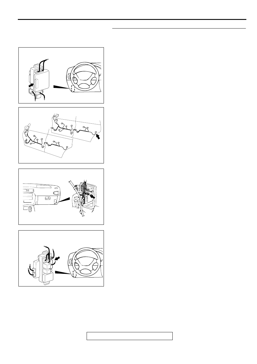
STEP 13. Check the harness wires between ETACS-ECU 
connector C-86 and rear door lock actuator (RH) connector 
E-10.

AC003080 AD

JUNCTION BLOCK
(REAR VIEW)

CONNECTOR: C-86

AC003086AJ

DOOR

CONNECTOR: E-10

AC003415 AC

CONNECTOR: C-71

CONNECTOR
BLOCK (RH)

AC003082 AF

JUNCTION BLOCK
(FRONT VIEW)

CONNECTOR: C-78

SWS DIAGNOSIS

TSB Revision

SIMPLIFIED WIRING SYSTEM (SWS)

54B-56

NOTE: After checking junction block connector C-78 and 
intermediate connector C-71 and D-07, check the wires. If 
junction block connector C-78 and intermediate connector C-71 
and D-07 are damaged, repair or replace them. Refer to 
GROUP 00E, Harness Connector Inspection 

P.00E-2

 .

Q: Are the harness wires between ETACS-ECU connector 

C-86 and rear door lock actuator (RH) connector E-10 in 
good condition?
YES : 
Replace the ETACS-ECU. All doors should be locked 

or unlocked.

NO :  Repair them. All doors should be locked or unlocked.

Inspection Procedure C-3: Central door locking system: All the doors do not lock or unlock with just 
the door lock switch operation.

TECHNICAL DESCRIPTION (COMMENT)
The door lock switch (built into the power window 
switch) or the ETACS-ECU may be defective.

TROUBLESHOOTING HINTS

Malfunction of the power window switch (door 
lock switch)

Damaged harness wires or connectors

DIAGNOSIS

Required Special Tools:

MB991502: Scan Tool (MUT-II) 

MB991529: Diagnostic Trouble Code Check Harness

STEP 1. Check method of the input signal

Q: Which is to be used, the scan tool or the voltmeter to 

check the input signal?
Scan tool MB991502 : 
Go to Step 2.
Voltmeter : Go to Step 3.

STEP 2. Check the input signal (by using scan tool 
MB991502).
Check the input signals from the defective door lock switch.

CAUTION

To prevent damage to scan tool MB991502, always turn the 
ignition switch to the "LOCK" (OFF) position before 
connecting or disconnecting scan tool MB991502.
(1)Connect scan tool MB991502 to the data link connector.
(2)Check that the tone alarm of scan tool MB991502 sounds 

when the input signal enters.

Q: Does the tone alarm of scan tool MB991502 sound when 

the input signal enters?
YES : 
Replace the ETACS-ECU. All doors should be locked 

or unlocked by using the door lock switch.

NO :  Check the defective door lock switch input circuit. 

Refer to Inspection Procedure N-10 (

P.54B-237

).

AC003084 AI

CONNECTOR: D-07

AC003081 AB

16 PIN

MB991502

SWS DIAGNOSIS

TSB Revision

SIMPLIFIED WIRING SYSTEM (SWS)

54B-57

STEP 3. Check the input signal (by using a voltmeter).
Check the input signals from the defective door lock switch.
(1)Use special tool MB991529 to connect a voltmeter between 

ground terminal 4 or 5 and ETACS-ECU terminal 9 of the 
data link connector.

(2)Check that the voltmeter indicator deflects once when the 

input signal enters.

Q: Does the voltmeter indicator deflect?

YES : Replace the ETACS-ECU. All doors should be locked 

or unlocked by using the door lock switch.

NO :  Check the defective door lock switch input circuit. 

Refer to Inspection Procedure N-10 (

P.54B-237

).

Inspection Procedure C-4: Central door locking system: All the doors do not lock or unlock with just 
the door lock key cylinder key operation.

TECHNICAL DESCRIPTION (COMMENT).
The door lock key cylinder switch or the ETACS-ECU 
may be defective.

TROUBLESHOOTING HINTS

Malfunction of the door lock key cylinder switch

Damaged harness wires or connectors

DIAGNOSIS

Required Special Tools:

MB991502: Scan Tool (MUT-II)

MB991529: Diagnostic Trouble Code Check Harness

STEP 1. Check method of the input signal

Q: Which is to be used, the scan tool or the voltmeter to 

check the input signal?
Scan tool MB991502 : 
Go to Step 2.
Voltmeter : Go to Step 3.

STEP 2. Check the input signal (by using scan tool 
MB991502).
Check the input signal from the defective door lock key cylinder 
switch.

CAUTION

To prevent damage to scan tool MB991502, always turn the 
ignition switch to the "LOCK" (OFF) position before 
connecting or disconnecting scan tool MB991502.
(1)Connect scan tool MB991502 to the data link connector.
(2)Check that the tone alarm of scan tool MB991502 sounds 

when the input signal enters.

Q: Does the tone alarm of scan tool MB991502 sound when 

the input signal enters?
YES : 
Replace the ETACS-ECU. All doors should be locked 

or unlocked by using the door lock key cylinder 
switch.

NO :  Check the door lock key cylinder switch input circuit. 

Refer to Inspection Procedure N-8 (

P.54B-212

).

AC003083

16 PIN

AB

ETACS-ECU
TERMINAL

GROUNDED TERMINAL

MB991529

AC003081 AB

16 PIN

MB991502

SWS DIAGNOSIS

TSB Revision

SIMPLIFIED WIRING SYSTEM (SWS)

54B-58

STEP 3. Check the input signal (by using a voltmeter).
Check the input signal from the defective door lock key cylinder 
switch.
(1)Use special tool MB991529 to connect a voltmeter between 

ground terminal 4 or 5 and ETACS-ECU terminal 9 of the 
data link connector.

(2)Check that the voltmeter indicator deflects once when the 

input signal enters.

Q: Does the voltmeter indicator deflect?

YES : Replace the ETACS-ECU. All doors should be locked 

or unlocked by using the door lock key cylinder 
switch.

NO :  Check the door lock key cylinder switch input circuit. 

Refer to Inspection Procedure N-8 (

P.54B-212

).

Inspection Procedure C-5: Central door locking system: All the doors do not lock with just the 
driver's inside lock knob lock operation.

TECHNICAL DESCRIPTION.
The driver's door lock actuator switch or the ETACS-
ECU may be defective.

TROUBLESHOOTING HINTS

Malfunction of the driver's door lock actuator 
switch

Damaged harness wires or connectors

DIAGNOSIS

Required Special Tools:

MB991502: Scan Tool (MUT-II) 

MB991529: Diagnostic Trouble Code Check Harness

STEP 1. Check method of the input signal

Q: Which is to be used, the scan tool or the voltmeter to 

check the input signal?
Scan tool MB991502 : 
Go to Step 2.
Voltmeter : Go to Step 3.

AC003083

16 PIN

AB

ETACS-ECU
TERMINAL

GROUNDED TERMINAL

MB991529


Content   ..  663  664  665  666   ..