Mitsubishi Galant. Manual - part 656
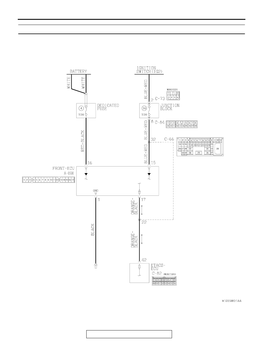
SWS DIAGNOSIS
TSB Revision
SIMPLIFIED WIRING SYSTEM (SWS)
54B-19
DTC 13: Front-ECU fault
AC004199
Front-ECU Power Supply and SWS Communication Circuit
|
|
|
SWS DIAGNOSIS TSB Revision SIMPLIFIED WIRING SYSTEM (SWS) 54B-19 DTC 13: Front-ECU fault AC004199 Front-ECU Power Supply and SWS Communication Circuit |